- 7.6.1. What are Features?
- 7.6.2. Listing of all possible features in the "3D history " docking window
- 7.6.2.1. Timeline
- 7.6.2.2. Fixed plane
- 7.6.2.3. Reference Plane
- 7.6.2.4. Sketch
- 7.6.2.5. 2D drawing
- 7.6.2.6. Base extrude / Base rotate
- 7.6.2.7. Cut extrude / Cut rotate
- 7.6.2.8. Extended Extrude/Cut functionality
- 7.6.2.9. Sweep base / Sweep cut
- 7.6.2.10. Grp Pattern / Pattern
- 7.6.2.11. Pipe
- 7.6.2.12. Blend ( add chamfer/rounding...)
- 7.6.2.12.1. What is the purpose of the Blend Feature
- 7.6.2.12.2. What is NOT the purpose of the Blend Feature
- 7.6.2.12.3. Basics - Create chamfer or fillet
- 7.6.2.12.4. General tips & notes
- 7.6.2.12.5. What should be considered
- 7.6.2.12.5.1. All blends, whose edges meet, have to be made as one blend
- 7.6.2.12.5.2. Blends in pattern
- 7.6.2.12.5.3. Tangent continuous
- 7.6.2.12.5.4. Preview display and edge visualization for chamfer/rounding
- 7.6.2.12.5.5. Face selection
- 7.6.2.12.5.6. Combination of Sweep and Blend
- 7.6.2.12.5.7. Representation of chamfer/rounding in various CAD systems
- 7.6.2.12.5.8. Very small radius for inch models
- 7.6.2.12.6. Not supported installation situations
- 7.6.2.12.6.1. Function "Create new sketch on marked area " requires at least one edge without blend
- 7.6.2.12.6.2. Several intersecting chamfers/fillets and Blend feature in addition
- 7.6.2.12.6.3. Edges resulting from Blends
- 7.6.2.12.6.4. Maximum radius of chamfer/rounding
- 7.6.2.12.6.5. Blends whose edges meet with different size each
- 7.6.2.12.6.6. Combination of a fillet and a chamfer
- 7.6.2.12.6.7. Radius of chamfer/fillet larger than distance to adjoining geometry
- 7.6.2.13. Text Feature
- 7.6.2.14. Texture label
- 7.6.2.15. Drill Feature
- 7.6.2.16. Multi Solid
- 7.6.2.17. Display specific calculation status
- 7.6.3. Multiply used commands
- 7.6.4. Context menu Name of the component
- 7.6.5. Solid context menu
- 7.6.6. Context menu base plane (Plane XY, ZX, YZ)
- 7.6.7. Context menu Reference Plane
- 7.6.7.1. Edit...
- 7.6.7.2. New sketch...
- 7.6.7.3. New 2D drawing...
- 7.6.7.4. New guiding curve...
- 7.6.7.5. Create pipe...
- 7.6.7.6. Create text...
- 7.6.7.7. Dependencies
- 7.6.7.8. Insert new plane...
- 7.6.7.9. Rename...
- 7.6.7.10. Paste sketch
- 7.6.7.11. Delete Plane (Plane Feature)
- 7.6.7.12. Fade in (Plane Feature)
- 7.6.7.13. Select new reference
- 7.6.7.14. Set mark
- 7.6.7.15. Copy to...
- 7.6.7.16. Condition
- 7.6.7.17. Deactivate/activate
- 7.6.8. Sketch context menu
- 7.6.8.1. Edit...
- 7.6.8.2. Solids -> Extrude... / Rotate..
- 7.6.8.3. Cut -> Extrude... / Rotate..
- 7.6.8.4. Create sweep base
- 7.6.8.5. Create sweep cut
- 7.6.8.6. Copy (only sketch)
- 7.6.8.7. Cut (including dependencies)
- 7.6.8.8. Rename...
- 7.6.8.9. Convert to guide curve...
- 7.6.8.10. Delete...
- 7.6.8.11. Show error...
- 7.6.8.12. Dependencies...
- 7.6.8.13. Construction sketch
- 7.6.8.14. Duplicate sketch
- 7.6.8.15. Select new reference
- 7.6.8.16. Set mark
- 7.6.8.17. Copy to...
- 7.6.9. Context menu "Base extrude/rotate" or "Cut extrude/rotate"
- 7.6.9.1. Edit...
- 7.6.9.2. Select all surfaces
- 7.6.9.3. Rename...
- 7.6.9.4. Delete...
- 7.6.9.5. Show error...
- 7.6.9.6. Dependencies...
- 7.6.9.7. Feature attributes...
- 7.6.9.8. Apply pattern
- 7.6.9.9. Convert to section /
- 7.6.9.10. Set mark
- 7.6.9.11. Copy to...
- 7.6.9.12. Condition
- 7.6.9.13. Activate/deactivate
- 7.6.10. Filter
- 7.6.11. Level of detail
The 3D History docking window is a central "showplace" within the PARTdesigner. Its context menus are used to call up the Sketcher (with Sketch History [Sketch history] ) and create the component.
![Calling up the sketcher via the 3D history [3D History]](https://webapi.partcommunity.com/service/help/latest/pages/jp/partwarehouse/doc/resources/img/img_5c053e7558164874a206556f37f6a9b3.png)
In addition, the history documents all design steps (features ) so that the respective component structure can be traced and possibly modified at a later date.
For each entry the most important actions are directly displayed once the mouse cursor is moved over the line. When clicking on the respective icon you can save calling the context menu.
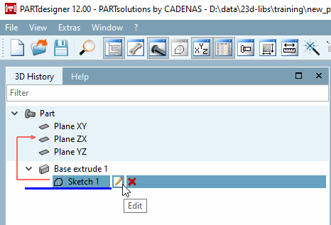
All commands available for a function can be found in the context menu. The context menu commands are explained in the following sections.
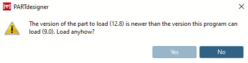
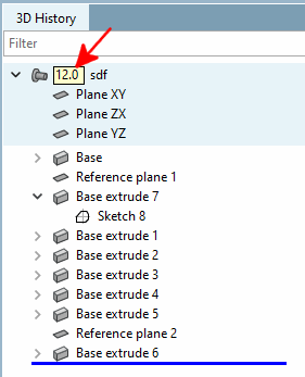
If a feature requires a minimum version, this is displayed next to the component name (e.g. 12.0, 12.4, 12.8, etc.).
When opening such a part in a V11, a message is displayed there. To avoid problems, you should NOT load the part in V11