
- 2.1.7.1. Determine characteristic in "Table" view
- 2.1.7.1.1. Full-text search in table
- 2.1.7.1.2. Show/hide variable groups
- 2.1.7.1.3. Call up table settings
- 2.1.7.1.4. Columns with value range fields
- 2.1.7.1.5. Preview images adjustable in size
- 2.1.7.1.6. Show preview images in parts view per line
- 2.1.7.1.7. Show graphics in table
- 2.1.7.1.8. Ascending/descending column sorting
- 2.1.7.1.9. Adjust column width
- 2.1.7.1.10. Show topology variables in table
- 2.1.7.1.11. Filter table
- 2.1.7.1.11.1. Filter table by search
- 2.1.7.1.11.2. Filter table via input fields in column header
- 2.1.7.1.11.3. Table filtered by accessory part
- 2.1.7.1.11.4. Use preferred rows filter
- 2.1.7.1.11.5. Example: Using filters
- 2.1.7.1.11.6. Parts that should be avoided
- 2.1.7.1.11.7. DIN 962 option
- 2.1.7.1.11.8. Hide columns
- 2.1.7.1.12. Additional information /-functions
- 2.1.7.1.13. Material selection
- 2.1.7.2. Determine characteristic in "Vertical" view
- 2.1.7.3. Determine characteristic in the 3D view
- 2.1.7.4. Docking window "References "
- 2.1.7.5. Docking window " Structure "
- 2.1.7.6. Docking window "3D view"
- 2.1.7.6.1. 3D view toolbar
- 2.1.7.6.2. Determine level of detail
- 2.1.7.6.3. Measuring 3D parts
- 2.1.7.6.4. Measuring grid
- 2.1.7.6.5. Show Dimensionings
- 2.1.7.6.6. Change characteristic via dimension labels
- 2.1.7.6.7. Define section cut...
- 2.1.7.6.8. Component designation (standard designation [NB ] / parts list designation [LINA ])
- 2.1.7.7. Docking window " Technical specifications "
- 2.1.7.8. Docking window "Parts information "
- 2.1.7.9. Docking window "Topology information "
- 2.1.7.10. Docking window "RFQ" (Request for Quotation)
As soon as you double-click on a project in the part selection [Part selection] (e.g. part  or assembly
  ), the user interface switches to the parts view [Part view].
In the part view you can specify the characteristic of the part.
The user interface is organized with docking windows. The following figure shows an overview of these.
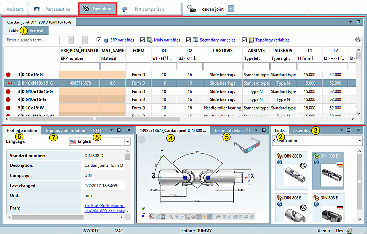
Table (the respective standard designation of the loaded part is displayed on the tab)
As sub-areas, you will again see two dockings, which represent two different modes for determining the characteristic.
References [Links] to related objects (see Section 2.1.7.4, “ Docking window "References " ”)
Structure [Assembly] / parts list [Bill of material] (see Section 2.1.7.5, “ Docking window " Structure " ”)
3D preview [Preview 3D] of the object (see Section 2.1.7.6, “Docking window "3D view" ”)
Technical specifications [Technical details] with dimensioned images (see Section 2.1.7.7, “ Docking window " Technical specifications " ”)
Parts information [Part information] (see Section 2.1.7.8, “Docking window "Parts information " ”)
Topology information (see Section 2.1.7.9, “Docking window "Topology information " ”)
Optionally, other dockings are displayed:
2D derivation (see Section 2.1.10, “ Create 2D derivation ”)