To be able to use components (such as valves / fittings) in planning systems (e.g.: Revit) accordingly it is required to set specific properties in the Revit classification.
For this first the adequate Revit Family Template has to be set:
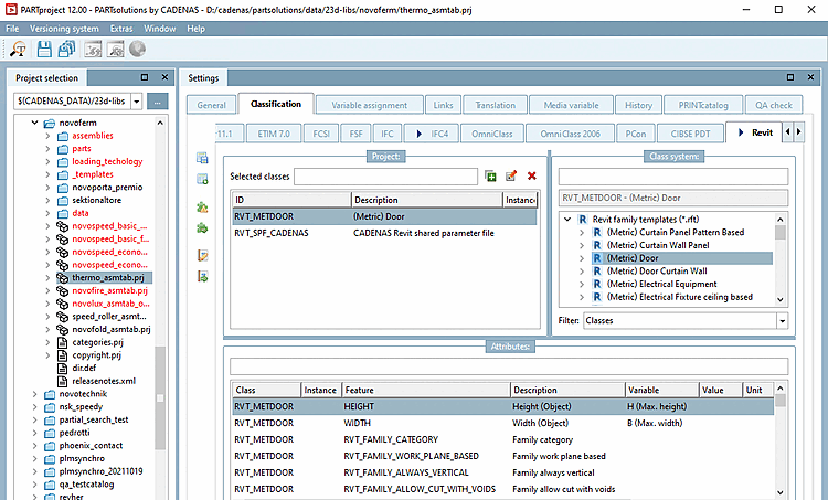
Start PARTproject and navigate via the directory structure to the component that is to be equipped with the appropriate class.
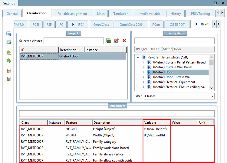
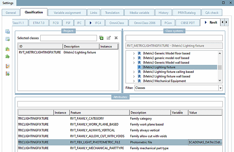
Open the Classification tab page and then the Revit tab page.
Select the class. (In the illustration above, (Metric) Door was selected as an example)
Listing of all currently available Revit family templates (*.rft):
![[Note]](https://webapi.partcommunity.com/service/help/latest/pages/jp/ecatalogsolutions/doc/images/note.png)
Each template of the Revit classification has its specific attributes.
Most templates in Revit or classes in 3Dfindit have the following 5 characteristics in the Revit classification. Additional information can be added, e.g. width and height.
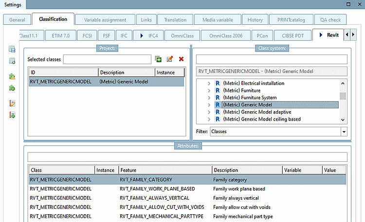
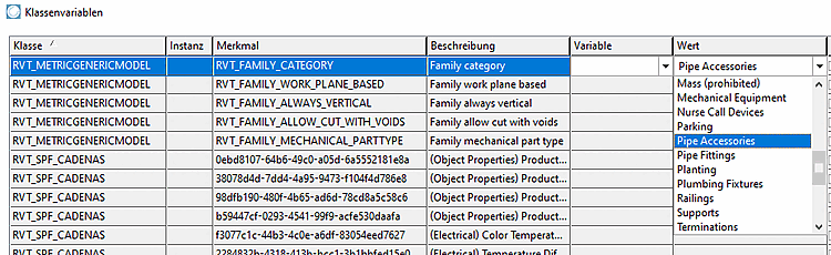
Family category: The family category defines which class/category a part will have in Revit.
Family work plane based: ... defines that the object can be placed using the 3 default work planes
Family always vertical: ... defines whether an object should always be placed "vertically".
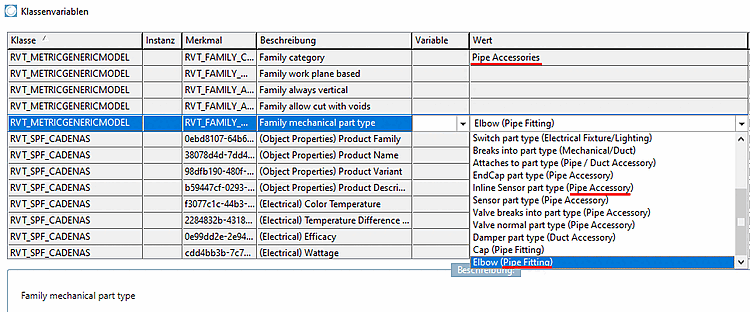
This property sets the functionality of the component e.g. when being used in a piping specification. There are pre-defined values, which are set according to the correct "Family category" (the category is described in brackets).
In the list field, set the desired value.
For the MEP[8]-field, mainly the following two values are used:
Example: For valves that divide a pipe into two sections, the recommendation Valve breaks into part type (Pipe Accessory) should be used.
A detailed reference (which part type creates which function) is available on the Autodesk help-site:
https://knowledge.autodesk.com/support/revit-products/learn-explore/caas/CloudHelp/cloudhelp/2018/ENU/Revit-Customize/files/GUID-54F9DD0A-6F46-4B52-8F58-B8FA630F14EA-htm.html
Revit family templates (*.rft) with corresponding attributes :
Details on this can be found under Section 3.5.4.2.1.1, “Revit: Load IES files in RFA (lighting fixtures)”.
For doors width and height attributes define the shell dimension.
Wall thickness – incl. plaster (as the door frame cannot react to the wall-thickness)
Wall opening width and height (must be wider and higher than the door leaf width/height because of mounting spaces) Common values for added spacing are: +35mm width and +17.5mm height. These values must be worked out and finalized with the manufacturer in the project workshop.
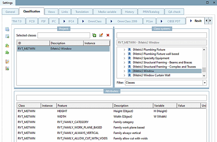
For windows, width and height features define the shell wall cut-out.
![[Important]](https://webapi.partcommunity.com/service/help/latest/pages/jp/ecatalogsolutions/doc/images/important.png)