7.8.
Docking window " Variable manager"
7.8.10.
Variable manager - The individual parameters
|  |
| Prev | Next |
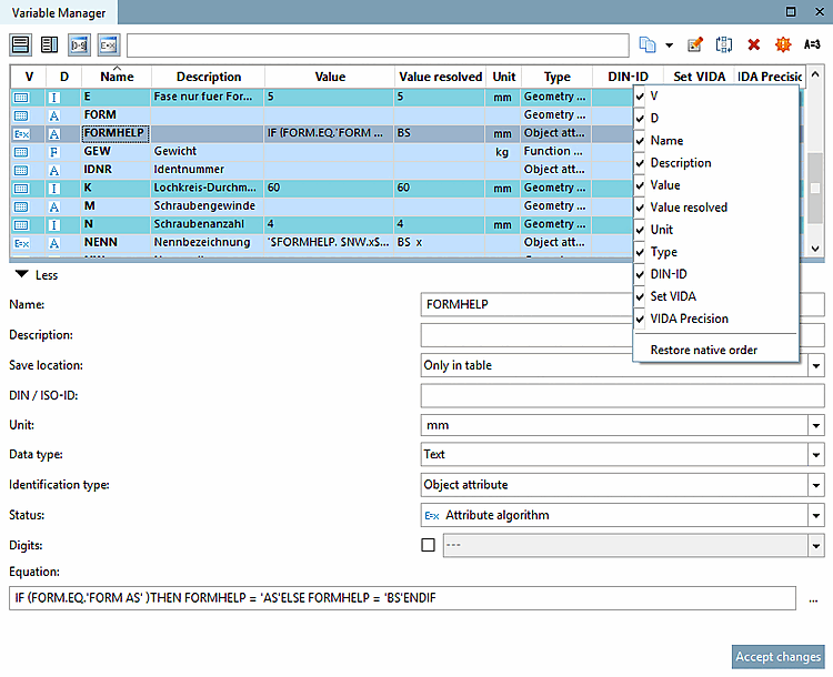

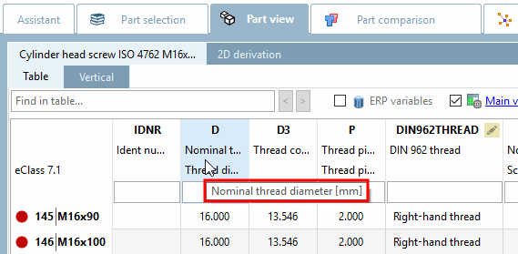
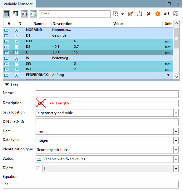
Name (variable name ) (mandatory for each storage location option): Enter the variable name.
The abbreviation entered in this field is displayed in the PARTdataManager in the column header of the table.
Description (variable description ) (mandatory for each storage location option): As the variable name is limited to 10 characters, you can add a descriptive text to the variable in the Description field, which makes it easier to identify.
The contents of the Description field are displayed in the PARTdataManager in the column subtitles of the table. If you move the mouse over the column header, the full text is displayed in the tooltip. Only a limited width is available in the column header itself.
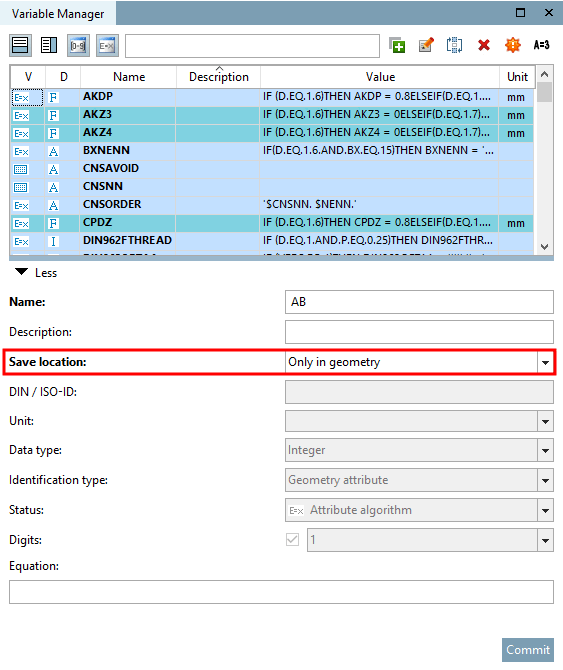
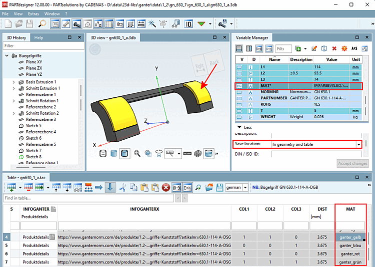
Storage location [Save location] (must be selected): Immediately recognizable by the color.
 Only in geometry: With this selection, the data is saved in the 3db file.
If no value ranges [Value ranges] and no feature algorithms [Attribute algorithms] are required and no specific settings such as type identification [Identification type] are to be set, this option is sufficient.
 Only in table: In this mode, the data is saved in the tab/tac file.
Table mode is required to create tables [Table], value ranges [Value ranges] and characteristic algorithms [Attribute algorithms].
 In geometry and table: With this selection, the data is saved both in the tab/tac file and in the 3db file.
If variables were initially only created with the Only in geometry option (in order to use them "quickly" for creating a 3D model), it is later necessary to save them in the tab/tac file in order to link them to the table and "fill" them dynamically.
If only the table is created initially, it is sufficient to select the Only in table option. Later, the variables that are required for creating the model (in the Sketcher) must also be saved in the 3db file.
To do this, select the option In geometry and table. The data is then saved both in the 3db file and in the tab/tac file.
Detailed information on the various storage location modes [Save location] can be found at Section 7.8.11, “ Storage location: Only in geometry | Only in table | In geometry and table ”.
DIN-ID [DIN / ISO-ID] (only for storage location [Save location] "
Only in table " or "
In geometry and table "):
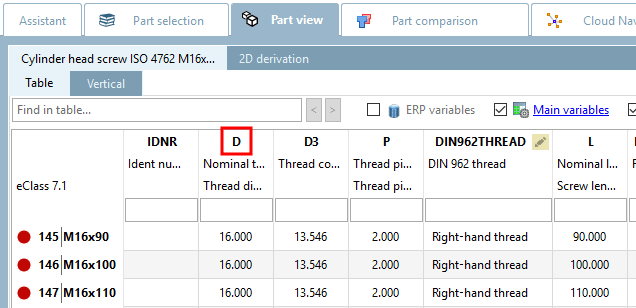
The DIN ID contains the dimensional letter from the dimensional and/or product standard, e.g. D1 for the nominal diameter [Nominal diameter] of a screw. Dimensional letters, such as Greek letters (alpha), can also be written out as a word.
Unit (only for storage location [Save location] "
Only in table " or "
In geometry and table "):
Unit that is used by default for this variable in the standard. As long as no changes are made, mm automatically appears here.
The contents of the Unit field are transferred to the column subtitle of the table.
Data type (only for storage location [Save location] "
Only in table " or "
In geometry and table "): Display in table column D.
Text is useful for printouts that should contain all characters, but text variables cannot be used for the calculation.
The Integer setting only allows numerical values. It must be used for variables whose values are used in calculations.
The Decimal number setting only allows numerical values. It must be used for variables whose values are used in calculations.
Type identification [Identification type] (only for storage location [Save location] "Only in table [Only in table] " or "In geometry and table [In geometry and table] "): Display in the table column Type.
The differentiation of characteristics according to characteristic types is particularly important for ERP/PDM integration!
Details on this can be found under Section 7.8.14, “ Identification type ”.
Status (only for storage location [Save location] "
Only in table " or "
In geometry and table "): Display in the table column V.
 Variable with [Variable with fixed values] fixed values (default setting)
Data are saved in the respective *.tab file. Table values can directly be edited in the PARTdesigner user interface.
A variable's value can directly be calculated by a so-called attribute algorithm.
Dependencies/conditions between variables can be expressed by attribute algorithms.
Example: „If D1=12, then D2=D3“. In this case you have to use an attribute algorithm.
How to create attribute algorithms is explained under Section 7.8.12, “ Attribute algorithms ”.
 Different options for value range
variable:
Different options for value range
variable:
Variables whose values lie within a defined range, e.g. "10 to 20", or for which several fixed values are available for selection, are assigned the status value range variable [Value range variable].
How to define value ranges can be read under Section 7.8.13, “ Value ranges ”.
![[Note]](https://webapi.partcommunity.com/service/help/latest/pages/jp/3dfindit/doc/images/note.png)
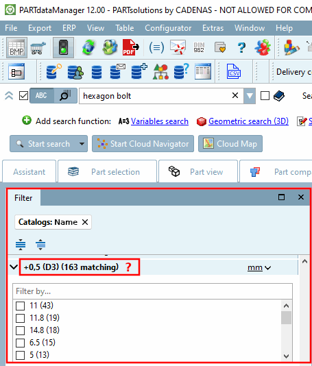
Note If you select Feature algorithm [Attribute algorithm] or one of the three value range variable options [Value range variable] as the status [Status], the corresponding variable/column in the table can be displayed [Show attribute algorithms] using the icon Show feature algorithms [Show attribute algorithms]
 or Show [Show value range] value ranges icon
 icon to show or hide it.
Places [Digits] (only for storage location [Save location] "
Only in table " or "
In geometry and table "): Display in the table column VIDA Precision
[88].
In this field you can determine the displayed decimal places.
If the Characteristic algorithm [Attribute algorithm] option or an option with value range variable (value range variable [Value range variable], value range variable with designation [Value range variable with naming], value range variable with graphics [Value range variable with graphics] ) has been selected under Status, the specification of decimal places (displayed under VIDA precision ) is optional [89]. With these options, you can activate or deactivate the specification of decimal places using the checkboxes.
If the Variable with fixed values option was selected under Status, the checkbox is grayed out and the specification of decimal places is mandatory. The Set VIDA table column shows the entry "true".
5.3
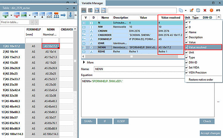
Formula [Equation] (mandatory for each storage location option [Save location] ): Display in table column Value.
Note The resolved values are always displayed in the corresponding column in the table [Table], but the unresolved values are displayed in the Variable Manager under Value.
However, you have the option of displaying the Value resolved column in the variable manager [Variable Manager]. The resolved values are also displayed here.
Enter the desired variable value under Formula [Equation].
This can be a fixed value or make the content dependent on other variables (2*D1, D1+D2, etc.).
Note Decimal values have to be set with point (wrong: 6,5 / correct: 6.5).
Complex functions can also be used. On this see under Section 7.8.12.8, “Mathematical functions (feature algorithm ) ”.
![[Tip]](https://webapi.partcommunity.com/service/help/latest/pages/jp/3dfindit/doc/images/tip.png)


| Note |
|---|---|
Changes are applied by clicking on . Changed parameters are displayed in bold until is clicked. If you want to restore the original status, change the line once without . | |
[88] VIDA means visualization display. However, eCATALOGsolutions only uses it for decimal numbers, for the display of decimal places.
According to the DIN V 4000 standard, according to which the tables are structured, VIDA is optional for characteristic algorithms and value ranges. See Set VIDA option (checkbox under Digits ).
VIDA precision means the number of decimal places for decimal numbers.
[89] According to the DIN V 4000 standard, according to which the tables are structured, VIDA is optional for characteristic algorithms and value ranges.