
The following examples provide a good overview of the basic functionality of PARTdataManager.
Detailed information on the individual steps can be found when following the links.
This shows you how to find a part using a full text search [Full-text search], then specify it using the  Part view and then export it to your CAD system.
Call up PARTdataManager from the 3Dfindit menu of your CAD system with the command Insert 3D or with 2D CAD systems with Insert 2D.
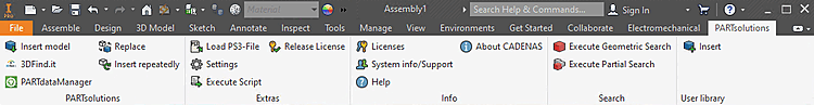
Detailed information on the CAD interfaces can be found at Chapter 1, Calling PARTsolutions from CAD systems.
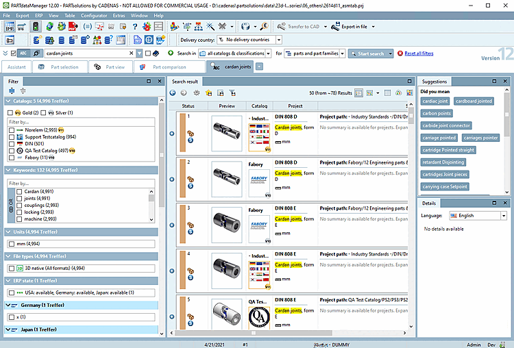
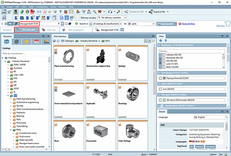
The following illustration shows the user interface that opens PARTdataManager opens.[27]
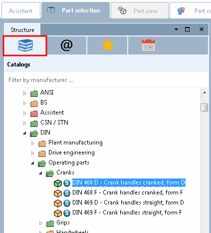
In principle, you can search for the desired component via the directory structure (for example on the Catalogs or Classes tab page), which is not considered in detail here in the example.
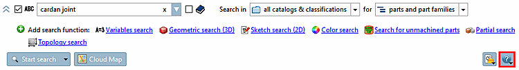
In this example, we will perform a full-text search [Full-text search]. This is opened and activated by default when the program is started.
Detailed information on all search methods is found under Section 2.1.6.4, “ Search methods ”.
Leave the default setting Search in "all catalogs & classifications " for "part families and individual parts [parts and part families] ".
You can find detailed information on this under Section 2.1.6.1.1, “ Search in...: Where? ” and Section 2.1.6.3, “ Search for Parts | Part families and Parts ”.
Enter the following in the input field:
wellengelenk
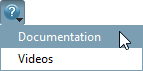
Detailed information on this can be found at Section 2.1.6.4.3, “ Full-text search ”, or directly from the user interface by clicking on Documentation.
 .
.-> The search results are listed on an own tabbed page. The label shows the search parameters.
On the component bitmaps (e.g.
 (component) or
  (assembly)[28] you can tell that you are at project level (the lowest level in the directory structure) by the icons.
Perform a double-click on the desired part.
The Parts view [Part view] dialog page opens.
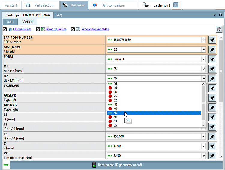
On the Part view tab page, you can now specify the characteristic of the part.
The following illustration shows setting options for the parts view [Part view]:
The default values when opening the Parts view [Part view] dialog page correspond to a middle table row (if ERP integration is available, a row with ERP number is loaded).[29]
In the following, the Vertical mode is used to specify the values.
All variables are listed one below the other.
In this example, D2 is set to the value 50.
The icon automatically changes from Several values are available for selection [There are some values possible at the moment.]
 to Filtered. Filtered variables restrict other selections [Filtered. Filtered variables restrict other selections.]
 .
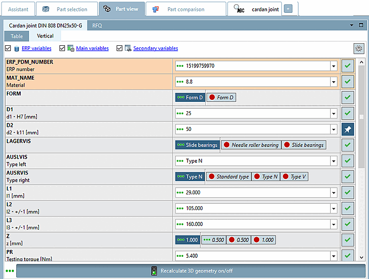
.-> Thus the value is filtered (pinned).
-> Selection completed [Selection done. There is only one value left to choose.] appears for dependent lines , there is only one possible value left [Selection done. There is only one value left to choose.]
 . In this example, this is the case for all other rows.
Detailed explanations of the symbols can be found at Section 2.1.7.2, “Determine characteristic in "Vertical" view ”.
In the 3D view, you can view and check the component in three dimensions.
For this you have many additional functions.[30] [31]
The magnifying glass [Magnifying glass] is also often
 is often helpful when details need to be viewed.
The Technical data [Technical details] docking window shows dimension views [Dimensioning views] (e.g. front view [Front view], side view [Side view] ) and display modes [Display mode].
If there are selection options select the desired one in the list field.
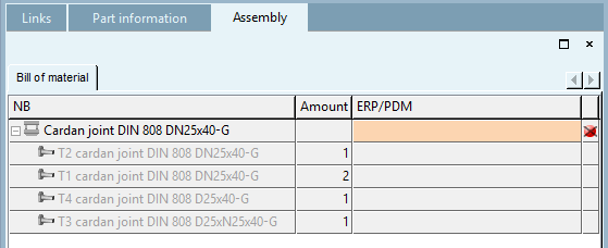
For assemblies [Assemblies], you can see the structure of the assembly in the docking window Structure [Assembly] -> Parts list [Bill of material] tab page. The individual parts are listed with the respective number [Amount].
Related components are displayed in the Links docking window.
If you are happy with your selection you can export the part or assembly to your CAD system.
To do this, click the Transfer to CAD button. [32]
![[Note]](https://webapi.partcommunity.com/service/help/latest/pages/jp/3dfindit/doc/images/note.png)
Note The button remains active, regardless of whether it is called from the 3Dfindit menu or you switch directly to the PARTdataManager.[a]
[a] If a "valid" model is open in the CAD system, the button in PARTdataManager is also automatically active.
Using Export to file [Export in file], you can also export the component to your hard disk in various formats.[33]
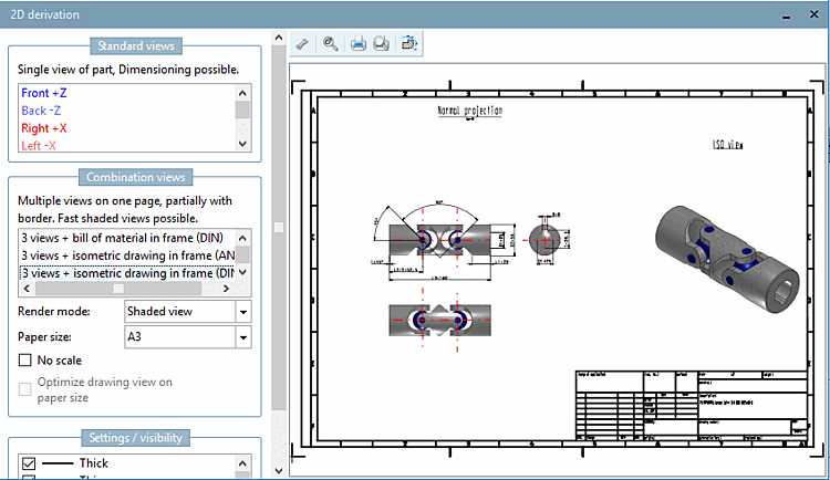
2D deriv [2D derivation] ation (optional)
If you want to export the component to a 2D CAD system, you must first create a 2D derivation.
To do this, click on the 2D view button
 .
.-> The 2D view dialog box appears.
Select a view. In this example, Frame DIN (BOM) is selected.[34]
Now export the part as described in the last point.
Note If the button
 Transfer to CAD button is clicked without a 2D derivation having been specified beforehand, a default derivation is transferred.
For information on setting options, see Section 2.1.8, “ Transfer to CAD (with and without interface) ”.
![PARTdataManager with "Parts selection [Part selection] " tab page](https://webapi.partcommunity.com/service/help/latest/pages/jp/3dfindit/doc/resources/img/img_4b4a1b59a0784a6096a3918ddfbfb313.png)
![Selection "Classifications [Classifications] "](https://webapi.partcommunity.com/service/help/latest/pages/jp/3dfindit/doc/resources/img/img_604354ad670a48b1b293a58037ea11b4.png)


![PARTdataManager with "Parts view [Part view] " tab page](https://webapi.partcommunity.com/service/help/latest/pages/jp/3dfindit/doc/resources/img/img_cd8986d78e5d4df6bc422dd658a72922.png)

![Part view with "Table [Table] " mode](https://webapi.partcommunity.com/service/help/latest/pages/jp/3dfindit/doc/resources/img/img_eaecdc28e91a48d5a46474f472fdbc6d.png)
![Part view with "Vertical [Vertical] " mode](https://webapi.partcommunity.com/service/help/latest/pages/jp/3dfindit/doc/resources/img/img_841fb75571de4173a71da18df301271b.png)
![3D view with magnifying glass [Magnifying glass]](https://webapi.partcommunity.com/service/help/latest/pages/jp/3dfindit/doc/resources/img/img_699b0dc4c64d4aa2ac8355fee4a3ba2f.png)
![Dimensioned view [Dimensioning view] "Front view [Front view] "](https://webapi.partcommunity.com/service/help/latest/pages/jp/3dfindit/doc/resources/img/img_0ca8dc9d240b4eac818413c8623db8e4.png)
![References [Links] (here with selection "Directory")](https://webapi.partcommunity.com/service/help/latest/pages/jp/3dfindit/doc/resources/img/img_cab2e62c023a4c659b25b8b4cf1a666d.png)

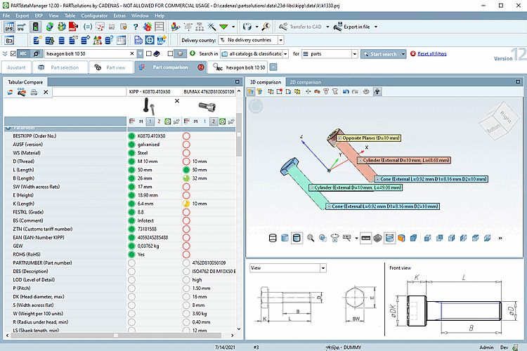
This illustrates how a search can directly deliver correct characteristics that can be checked both textually (table variables, topological characteristics and class characteristics) and geometrically in the 3D view in the component comparison [Part comparison] docking window, and how the desired part can be exported directly to the CAD system.
We carry out a full text search [Full-text search] with the following settings:
Current selection (ISO) [on the Catalogs tab page, select "Standard" -> "ISO"]
Full text search [Full-text search] with the following term:
sechskantschraube 10 50
sechskantschraube D>=10 D<=16 L=50
You can find detailed information on syntax under Section 2.1.6.4.3, “ Full-text search ” or inside the application with click on
 .
.
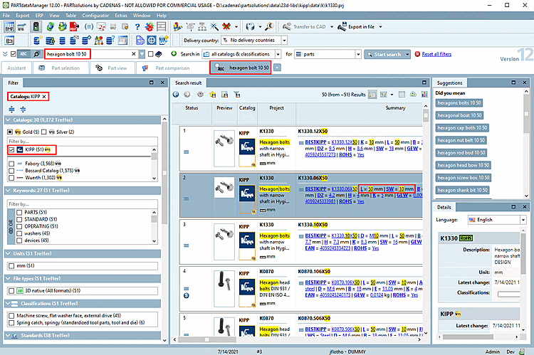
-> The view switches to the Search results tab page. Specific individual parts are already listed as hits. You can recognize this by the corresponding symbol
 .
.Due to the variable specification in the search results list only correct characteristics are displayed.
The variables are displayed in the Summary column. You can see here that only individual parts that correspond to the specification are displayed.
Also see Section 2.1.6.7, “ Search results ”.
A large number of filters are available in the Filter dialog area. In this example, the filter has been set for the manufacturer "Kipp". The filter options displayed are adjusted dynamically with each step.
Two hits should now be loaded into the component comparison [Part comparison]:
To do this, click on the Load as 1st component [Load as first part] icon for the first part
 and for the second part on the Load as 2nd [Load as second part] component icon
 .
.-> The Part comparison docking window opens. You can see the number of open parts on the tab.
You can now check the loaded components in many ways. You can find detailed information on this at Section 2.1.6.10, “ Part comparison ”.
Click on the Transfer to CAD [Export to CAD] icon for the desired part
 .
.-> The desired part is transferred into the CAD system via interface.
Detailed information on this can be found at Section 1.6.2, “ Insert from the standard and purchased parts library via "PARTdataManager"”.
[27] If the PARTdataManager opens with the Wizard [Assistant] window, click on "Search and part selection [Search and Part Selection] "; and if you activate "Save selection [Save selection] ", the Wizard window no longer appears at startup, but can be called up at any time via  in the toolbar at any time.
[28] These are the most common bitmaps. All others can be found under Section 2.1.14, “Legend: Used icons on catalog, directory, project level and part view ”.
[29] If you have searched with the setting Individual parts [Single parts]
setting, the values correspond exactly to the specification opened.
[30] Detailed information on the 3D preview [Preview 3D] can be found at Section 2.1.7.6, “Docking window "3D view" ”.
[31] Detailed information on the 3D context menu can be found under Section 2.1.7.6, “Docking window "3D view" ”.
[32] Information on all CAD integrations can be found at Chapter 1, Calling PARTsolutions from CAD systems.
[33] Detailed information on the export formats can be found under Section 2.1.9, “ Export to various file formats (without 3Dfindit interface) ”.
[34] You can find detailed information on this under Section 2.1.10, “ Create 2D derivation ”.