In the following you can find notes on page structure and function logic.
The upper page area with menu and toolbars is always visible. Which menus, menu items, buttons and toolbars are to be displayed can be completely controlled via a configuration file. See Section 1.7.7.2, “ Tweak menus, menu items, toolbars, buttons and context menu commands ” in ENTERPRISE 3Dfindit (Professional) - Administration.
The display in the lower area depends on the current tab selection.
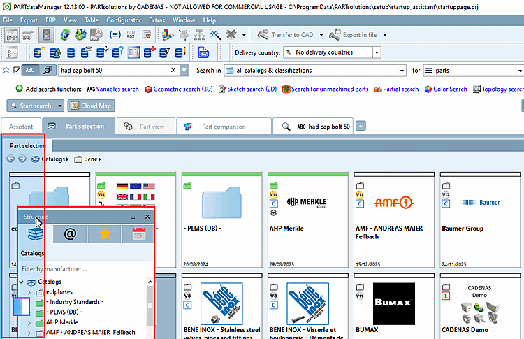
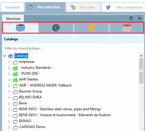
Fig. „ Parts selection [Part selection]: Start interface PARTdataManager“shows the start interface of PARTdataManager. For this you can at any time by clicking on the Parts Selection [Part selection] tab, where the last selected subsection is displayed again, i.e. not be sure to
 catalogues [Catalogs],
but possibly also
catalogues [Catalogs],
but possibly also  classifications [Classifications],
  favorites [Favorites],
 Open
projects [Opened projects].
Open
projects [Opened projects].
After a search has been carried out, the Search results Tabbed page is automatically loaded.
If a specific project is loaded, the user interface switches to the parts view [Part view]. All characteristics of the project are displayed here ( table [Table] or vertical [Vertical] view). Each characteristic can be checked using the 3D view. Technical drawings or dimensioning views, for example, are also displayed. The desired characteristic can be specified here before transferring to the CAD system.
![[Note]](https://webapi.partcommunity.com/service/help/latest/pages/jp/3dfindit/doc/images/note.png)
Note You can switch back and forth between the individual tab pages at any time by clicking on a tab.
Calling up the parts view [Part view] is optional. Specific characteristics can already be determined in the Parts selection [Part selection] dialog area.
Parts can then be transferred to the CAD system using or the Part comparison tab page can be opened first. Both a textual and 2D/3D check can be carried out here and the part can then be transferred to the CAD system.
The dialog area below the tabs (Assistant [Assistant], Part selection (with sub-areas Catalogs, Classifications, Favorites, History ), Part view, Part comparison, Search results ) is controlled by these tabs.
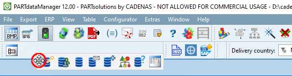
You can move toolbars by clicking on the handle using drag & drop.
The user interface is subdivided by docking windows.
You can arrange the windows as desired. Changes are saved and reloaded at the next start.
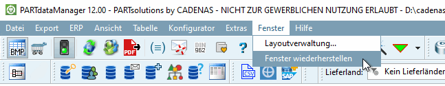
Perhaps you have moved the individual docking windows to try something out and now simply want to return to the default setting? Click on Restore window in the Window menu.
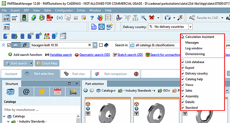
Part selection: You can show and hide the individual dockings using the context menu command in the menu and toolbar area.
Part view: You can show and hide the individual dockings using the context menu command above a window.
In order to perform positional changes click on the title bar of a docking window and draw it to the desired position with pressed left mouse key. If you release the mouse key outside the main window the docking appears as separate window so that you can move it to a second monitor if desired.
If you move the docking window to be moved over the tab area, the possible insertion area in which you can place the window is highlighted.
If you move the docking over the title bar of another docking window and release the mouse key there then the window is displayed with its own tab together with the other docking.
A detailed description of the placing method can be found under Section 2.1.5.4, “Placing method for dockings ”.

![Parts view [Part view]: Show and hide dockings](https://webapi.partcommunity.com/service/help/latest/pages/jp/3dfindit/doc/resources/img/img_e34aee038ad14d10904a079866ada36e.png)