It should only be classified according to the Placement Coordinate System (CNS_CP) method. Older components may still be classified according to Revit family template mapping (RVT_CP).
If both exists, the interface will use CNS_CP.
The following rules apply to both the CNS_CP_PLACE_PC and the RVT_CP classification:
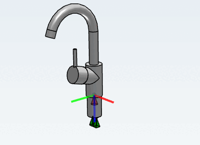
The Z-axis of the connection point (note, this corresponds to the flat side of the "pyramid") must point in the direction of the target surface in Revit.
For the vast majority of family templates, this is the "bottom" (=downwards).
Exceptions to the “bottom” surface are:
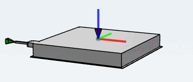
All templates "ceiling based" (flat side of the "pyramid" must point "upwards")
All templates "(....) wall based" (flat side of the "pyramid" must point in the direction of the wall, Y axis (green)=downwards
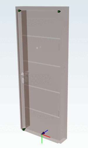
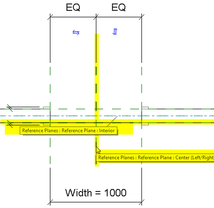
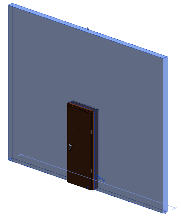
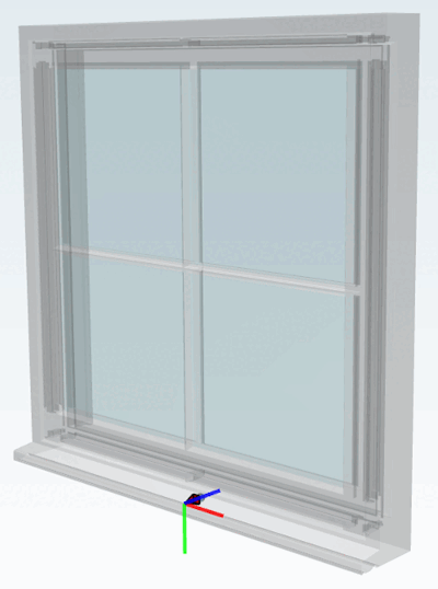
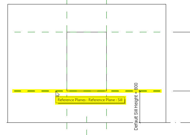
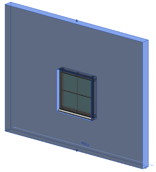
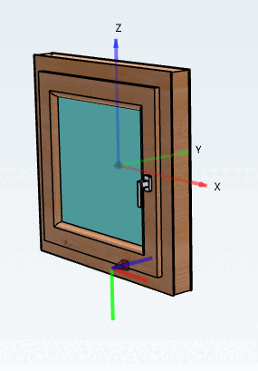
All "Door" and "Window" templates (flat side of the "pyramid" must point in the direction of the wall, Y axis (green)=downwards)
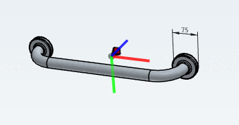
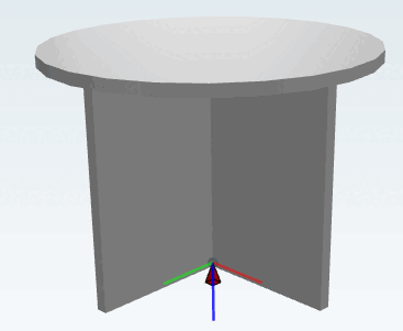
The connection point points to the bottom (Z), the X axis points right and the Y axis to the left.
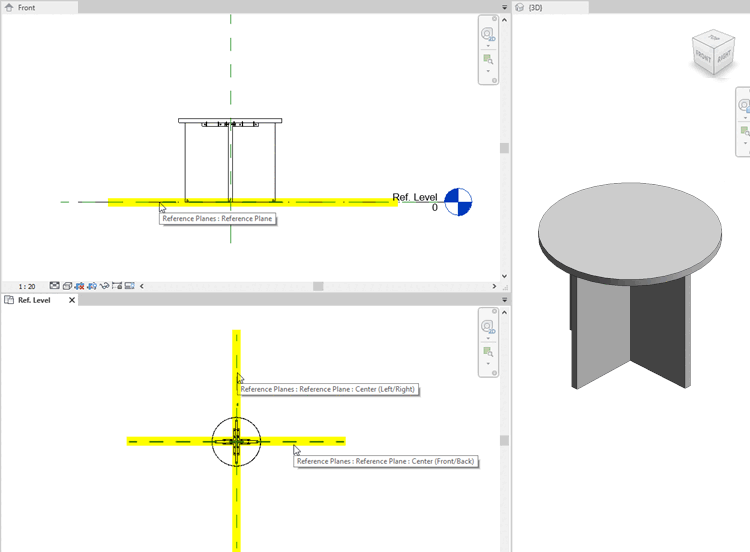
Products with the assigned Metric generic model class are placed as follows:
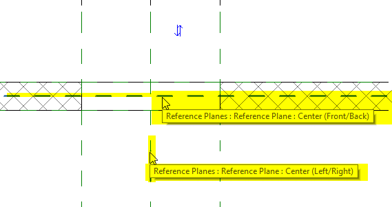
The X axis points towards the “Center(left/right)” plane.
The Y axis points towards the “Center(front/back)” plane.
The Z axis points towards the “Reference plane” (base plane).
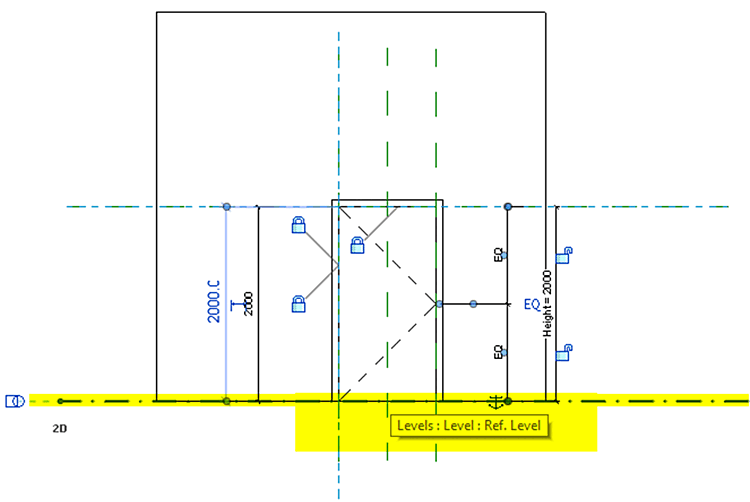
The connection point points to the wall (Z), the Y axis (green) points downwards and the X axis points to the right.
See also Section 3.5.2.6, “Sample objects” -> Doors.
The connection point points to the wall (Z), the Y axis (green) points downwards and the X axis points to the right. This is identical with the door template, but the placement of windows is done at the center reference plane of the wall.