Pipe accessories, such as valves must follow the VDI 3805 sheet #2 guideline. The sheet 2 guideline cannot be fully repeated due to copyright, but these are some key facts:
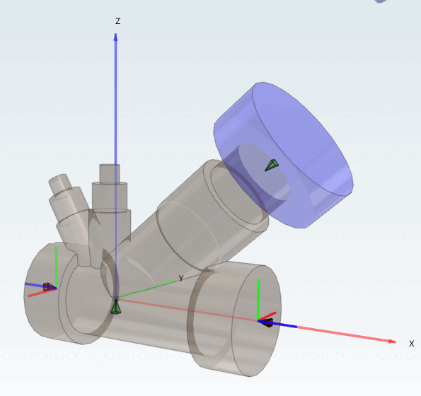
The geometry must have its 0/0/0 (X/Y/Z coordinate) point at the position where the center of the pipe intersects with the position of the valve.
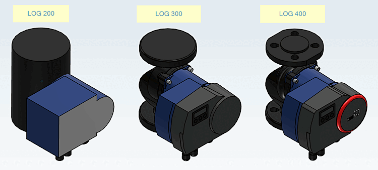
The geometry must follow the rule-based concept (in every case for LOG 200/300)
A placement connection point (Revit) must be available and positioned at 0/0/0 with Z-Axis pointing down (see above (Placement (Revit))
Connection points (for Piping) must follow the rules above:
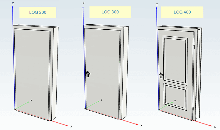
Doors (and windows) are very special and complex objects in buildings. In general, doors and windows should be modelled as parametric geometries (in all AEC-CADs). As CADENAS does not export parametric CAD objects, the following parameters for doors are mandatory.
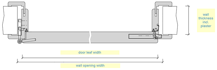
Wall thickness – incl. plaster (as the door frame cannot react to the wall-thickness)
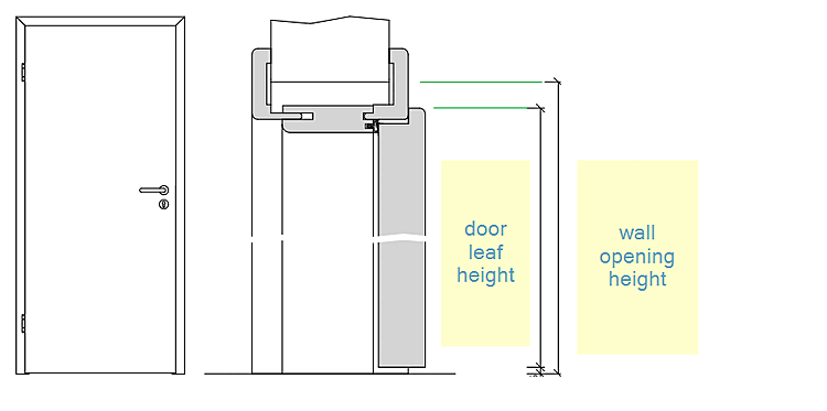
Wall opening width and height (must be wider and higher than the door leaf width/height because of mounting spaces) Common values for added spacing are: +35mm width and +17.5mm height. These values must be worked out and finalized with the manufacturer in the project workshop.