
A 3D solid must always be created on a 2D sketch. This 2D sketch is created in its own docking window, the Sketcher.
In the following, with the help of a simple cuboid, the procedure is explained step by step.[79]
Create a new project in PARTproject create a new project. You can find a small example of this at Section 5.5, “Create project - Small example from A to Z ”.
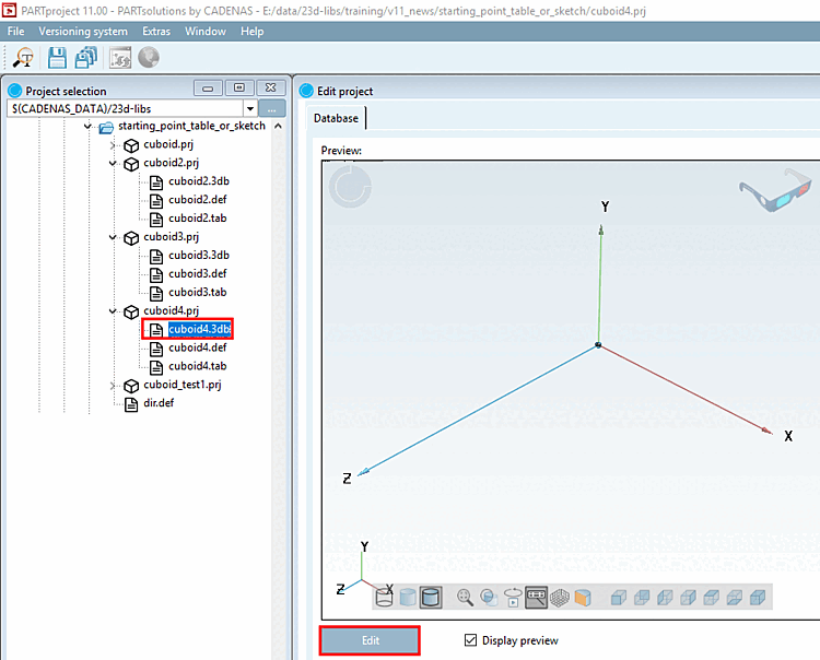
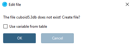
In the project to be edited select the *.3db file.
-> The Edit file dialog box opens.
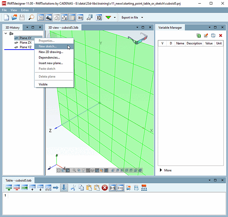
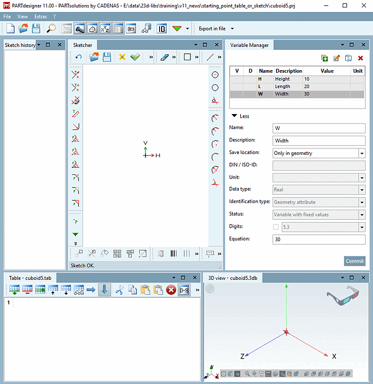
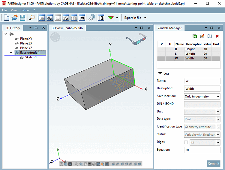
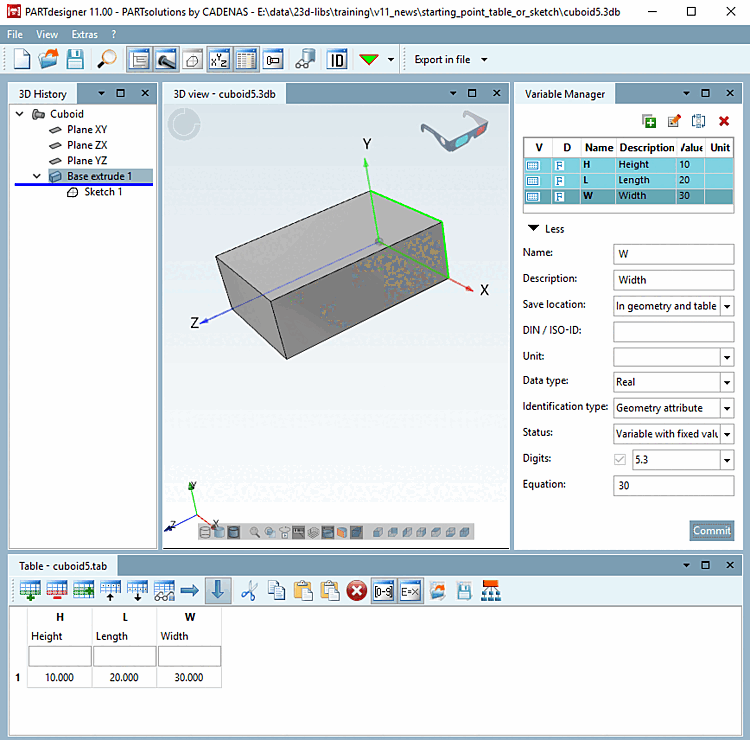
-> It opens PARTdesigner opens with the docking windows 3D History, 3D View [3D view], Variable Manager and Table.
![[Note]](https://webapi.partcommunity.com/service/help/latest/pages/jp/ecatalogsolutions/doc/images/note.png)
Note You can position the docking windows as you wish. See Section 2.1.5.4, “Placing method for dockings ” in PARTsolutions - User.
The 3D history [3D History] docking window contains the three basic levels for the construction sketches.
Click with the secondary mouse button on one of these layers (here XY) and select the menu item New sketch.... [New sketch...] in the context menu.
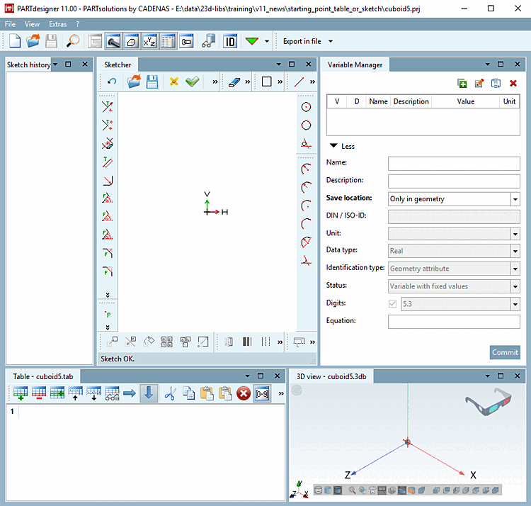
-> This command calls up the Sketcher.
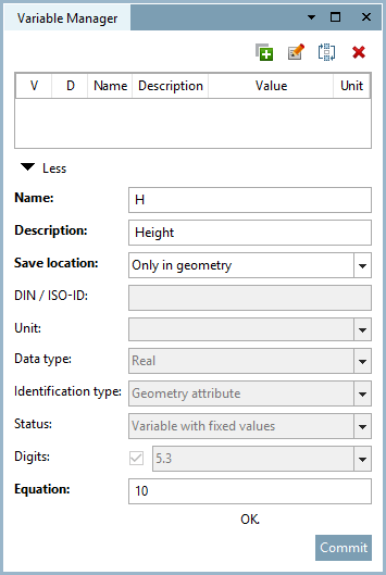
Create the variables L (Length), W (Width) and H (Height) for a cuboid in the variable manager [Variable Manager]. Details on the variable manager [Variable Manager] can be found at Section 7.8, “ Docking window " Variable manager" ”.
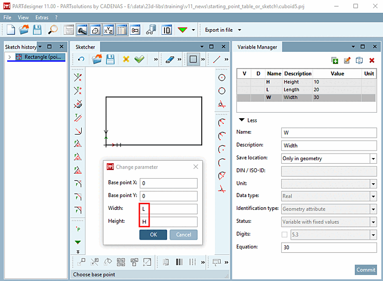
First, draw a rectangle which will be extruded later. Details on the sketcher can be found under Section 7.9, “ Docking window "Sketcher " ”.
Click on the Insert rectangle button
 .
.Set a center point by moving the cursor to the KO origin and simply fix it with a mouse-click.
When moving the mouse cursor, you can draw the rectangle. Fix the size of the rectangle by a simple mouse click.
The following happens simultaneously:
-> The design step appears in the wording in the Sketch history docking window.
-> The Change parameters [Change parameter] window opens in the drawing. Here you can specify the exact size and position of the drawing element.
Now use the corresponding variables for length [Length] and height [Height].
Click on the Apply changes [Accept changes] button
 button to confirm your entries.
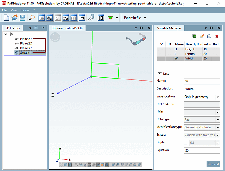
-> The design step Sketch 1 appears in the 3D history [3D History] docking window.
-> In the 3D view docking window, the rectangle lies on the XY plane.
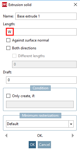
Click on Sketch 1 with the secondary mouse button and select the command Solids [Base] -> Extrude.... [Extrude...]
Determine the length [Length] by entering the variable W and confirm with .
-> In the 3D history [3D History] menu area, the Base rotate 1 construction step now appears in conjunction with Sketch 1.
-> In the 3D view, the rectangle with the value W is extruded into a cuboid.
Execute the Check part [Test part] function
 function.
-> The part's integrity is checked. This is of importance, because only then a faultless export to the different CAD systems is ensured. For details see Section 7.24.2, “ Test part ”.
Finally, click on the Save button
 .
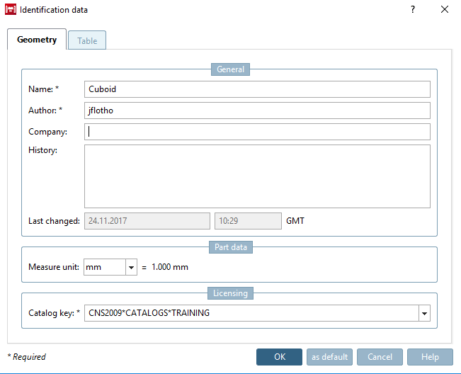
.-> The Identification details [Identification data] window is opened with the Geometry tab page.
Fill in the mandatory fields Component name [Part name], Author and Catalog key.
If a valid catalog key [Catalog key] is not specified, remains greyed out and cannot be saved.
The scheme for a valid catalog key [Catalog key] is as follows:[80]
CNS2009*CATALOGS*KATALOGNAME
Here in the training example, the catalog key [Catalog key] is
CNS2009*CATALOGS*TRAINING
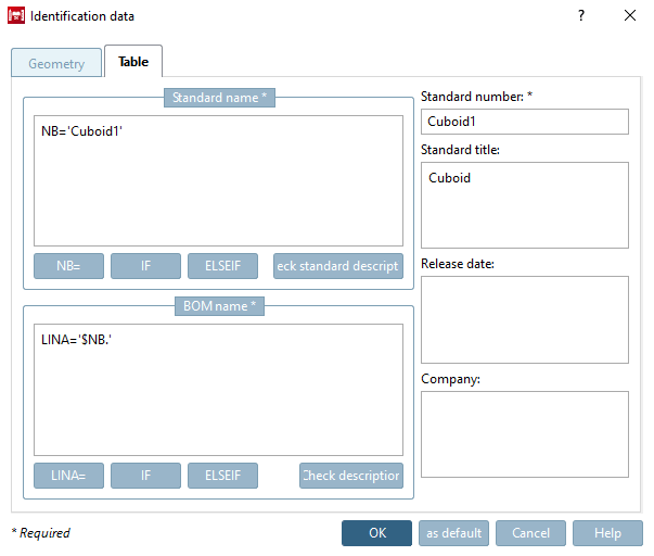
Fill in the mandatory fields Standard designation [Standard name], Parts list designation [Description for BOM] and Standard number. Details can be found at Section 7.18.9, “ Identification data ”.


![Solids [Base] -> Extrusion [Extrude...]..](https://webapi.partcommunity.com/service/help/latest/pages/jp/ecatalogsolutions/doc/resources/img/img_9f91624a6c3f4713bd8b26b5ec3547dc.png)
| Note |
|---|---|
If a table is to be created, it is necessary to change the storage location [Save location] of the individual variables in the variable manager [Variable Manager] from Only in geometry to In geometry and table.
You can recognize the storage location [Save location] by the corresponding color. Details can be found at Section 7.8.11, “ Storage location: Only in geometry | Only in table | In geometry and table ”. Simply select the desired variable, change the selection in the list field and confirm with . | |


A table with the default values from the variable manager is created immediately after switching to the " In geometry and table " storage location [Save location]. This can now be expanded at any time.
| ||||
| ||||