![[Note]](https://webapi.partcommunity.com/service/help/latest/pages/jp/ecatalogsolutions/doc/images/note.png)
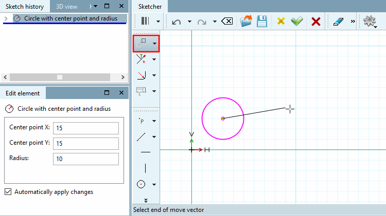
Move drawing element with the help of a vector
Select start point of the displacement vector [Choose start of move vector] / Select end point of the displacement vector [Select end of move vector]: You can select the start and end point at any point.
-> The element is then immediately moved by the length and direction of the vector.
In the Edit element window, adjust the vector coordinates X offset [x offset] and Y offset [y offset] if necessary. This allows you to position the element exactly.
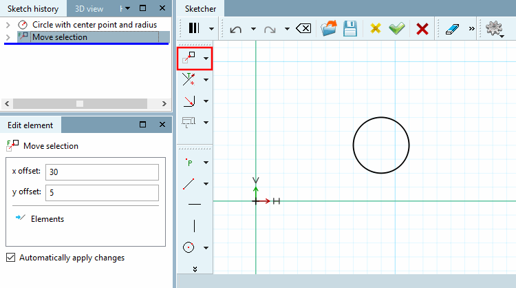
Copy and move drawing element using a vector (e.g. for several identical holes)
Select start point of the displacement vector [Choose start of move vector] / Select end point of the displacement vector [Select end of move vector]: You can select the start and end point at any point.
-> The element is immediately copied and moved according to length and direction of vector.
If necessary, adjust the vector coordinates X-Offset [x offset], Y-Offset [y offset] in the Edit element window. This allows you to position the element exactly.
You may also need to adjust the number [Number] of copies. By default, 1 copy is created initially. The figure below shows 2 copies.
The illustration shows the original and 2 copies, each shifted with an X offset [x offset] of 30 and a Y offset [y offset] of 5.
As an alternative to the function described above, you can also use
 Move selection while holding down the Ctrl key.
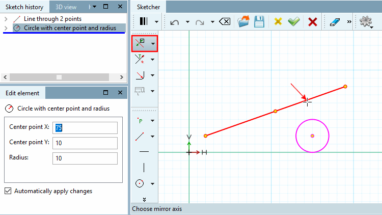
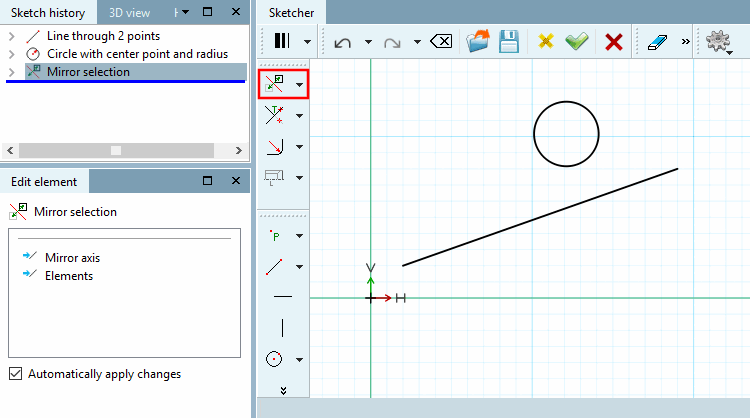
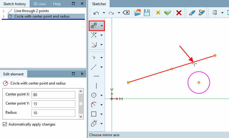
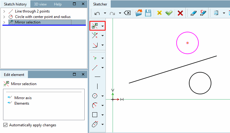
 Copy and mirror selection (Mirror selection and keep original)
Copy the drawing element and mirror it along an mirror.
As an alternative to the function described above, you can also use the
 Mirror selection while holding down the Ctrl key.
 Rotate selection (Rotate and delete original)
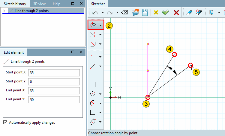
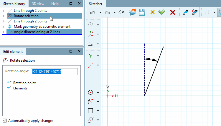
Rotate sketch element on a Point through a certain angle
Specify reference angle via point [Choose reference angle by point]: Determine the angle of rotation using any two reference points that span the angle.
Click on a point which determines the first reference line of the angle.
Specify angle of rotation via point [Choose rotation angle by point]:
Click on a point which determines the second reference line of the angle.
-> Once the second point is fixed the element is immediately rotated through the angle spanned by the two lines.
If necessary, correct the rotation angle [Angle of rotation] in the Edit element window. (If the second line was to the right of the first, a negative value is displayed, otherwise a positive one)
Rotate connection points: See next point below
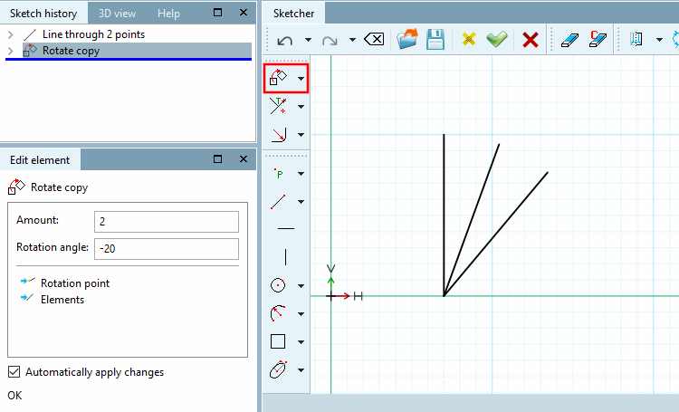
 Copy and rotate selection (Rotate and keep original)
Copy sketch element and rotate it on a Point through a certain angle.
Specify reference angle via point [Choose reference angle by point]: Determine the angle of rotation using any two reference points that span the angle.
Click on a point which determines the first reference line of the angle.
Specify angle of rotation via point [Choose rotation angle by point]:
Click on a point which determines the second reference line of the angle.
-> Once the second point is fixed the element is immediately rotated through the angle spanned by the two lines.
If necessary, correct the rotation angle [Rotation angle] in the Edit element window and enter the number [Amount] of desired copies under Number [Amount].
In this example the angle of rotation has been adjusted to "-20" and the number of copies to 2 (default is 1).
As an alternative to the function described above, you can also use the
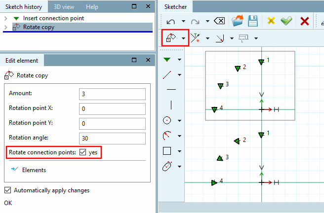
Rotate selection while holding down the Ctrl key.Connection points can also be rotated.
In this case, the corresponding function is also displayed. The connection point is then also rotated with the specified rotation angle [Rotation angle].
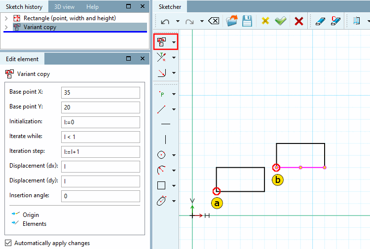
Copy sketch element for user defined variant
Mark all required sketch elements (multi selection with pressed Ctrl key). (Alternatively: frame elements with pressed Shift key.)
-> The element is marked in pink.
Use the secondary mouse button to click in the free space to deactivate previous functionality and then click on the
 Copy variant [Variant copy].
Choose reference point and insertion point for the selected Element (the selected group).(The snap signalizes whether a point is catched.)
-> The Edit element window opens.
Adjust the settings as desired:
Base point X: X-coordinate insertion point of the first copy
Base point Y: Y-coordinate Insertion point of the first copy
Initialization [Initializing]: Start value of the variable "I"
Advance [Iteration step]: Advance value (usually no change necessary; with 2, one element would always be skipped)
Displacement (dx): Element displacement in the direction of the X-axis per iteration step
Displacement (dy): Element displacement in the direction of the Y-axis per iteration step
Insertion angle: Rotation of the selected element (the selected group) by one angle per iteration step.
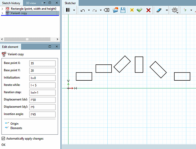
-> The copies of the element are placed according to the settings.
In below example five copies of the chosen element are created. The copies are shifted by 20 in the direction of x axis , 0 in the direction of y axis and rotated by 30° in each step of iteration.
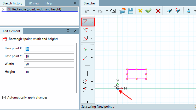
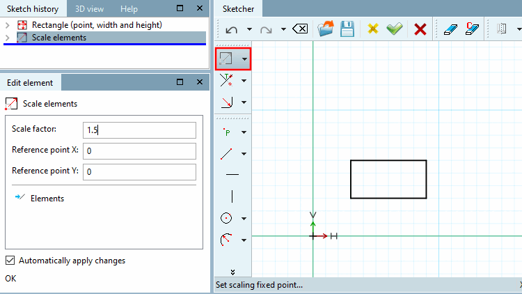
Select scaling fixed point [Set scaling fixed point...]...: The direction of the expansion depends on the selected fixed point.
Enter the scaling factor [Scale factor] in the input field.
Values greater than 1 increase the size of the original element, values less than 1 reduce the size of the original element.
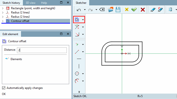
The contour offset [Contour offset] tool creates a duplicate of the contour with a scaling factor.
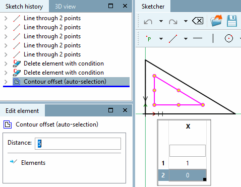
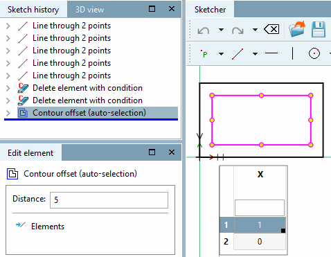
 Contour offset (auto-selection)
The contour offset [Contour offset (auto-selection)] tool (auto-selection) [Contour offset (auto-selection)] creates a duplicate of the automatically completed contour with a scaling factor (see Contour offset ). Selecting just one element is sufficient.
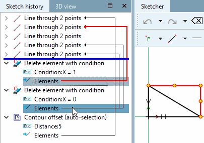
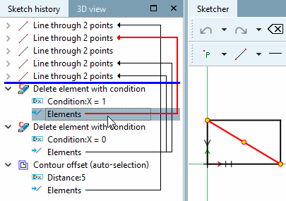
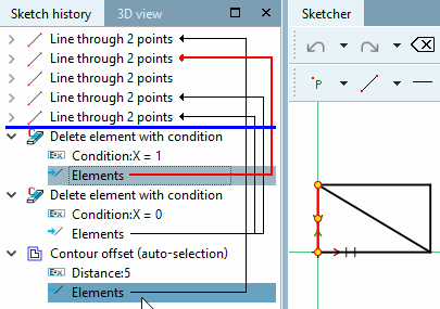
Assuming a sketch is modified by conditions that access table variables, Konturoffset [Contour offset] does not work because all selections must be available from the start.
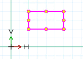
The two following figures show how once a triangle and once a rectangle is drawn.

![The illustration shows the original and 2 copies, each shifted with an X offset [x offset] of 30 and a Y offset [y offset] of 5.](https://webapi.partcommunity.com/service/help/latest/pages/jp/ecatalogsolutions/doc/resources/img/img_bff4e0e2bcf5474ba3d2491320e71e07.png)