
The measurement dialog [Measure dialog] is divided into the fields Element 1, Element 2 and Result and Fixings [Constraints].
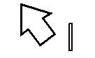
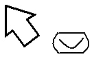
By calling the Measure command the mouse pointer gets an object related geometry symbol in the 3D view , which is signalizing the type of the touched element.
After you have clicked on two drawing elements (surface, edge, hole, etc.) in succession within the 3D preview [Preview 3D], an icon [Symbol] appears in the Element 1 and Element 2 fields.
In the following the possible geometry symbols are shown:
![[Note]](https://webapi.partcommunity.com/service/help/latest/pages/jp/ecatalogsolutions/doc/images/note.png) | Note |
|---|---|
The quickest way to determine the dimensions of a component is in the context menu of the 3D window via the menu item Measurement grid [Measuring grid]. See also Section 2.1.7.6.4, “ Measuring grid ”. | |
In the following example, two opposing planes have been clicked (see Fig. „2 planar planes selected“).
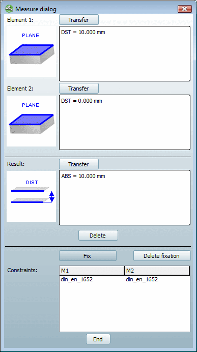
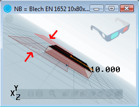
The two faces are at a specific distance of 10 mm, as shown symbolically in the Result area. The measure of distance (ABS = 10.000 mm) is displayed to the right of it.
The command is available for planar, parallel surfaces.
When changing the table row, the display of the dimensions in the 3D preview [Preview 3D] is retained.
With you can delete the fixation.
The command is required for classifying native parts.
Detailed information on this can be found under Transferring values from the Measurement dialog box.