Drawings can be enhanced with BMG layers according to DIN 4003. When exporting 2D DXF/DWG these layers transfer important information for Tooling and BIM, among others.
Prerequisite: CNS classification with corresponding data
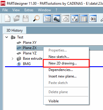
Click in the PARTdesigner 3D History docking window, click on the context menu command New 2D drawing.... [New 2D drawing...]
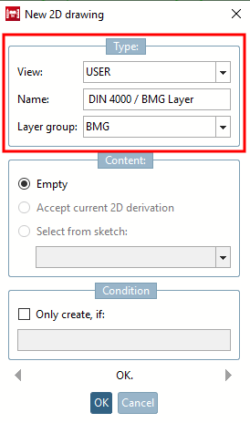
-> The 2D drawing dialog box opens.
Select the User option under View.
Enter e.g. DIN 4000 / BMG Layer under Name.
Select the BMG option under Layer Group [Layer group].
-> The Sketcher is opened. (The Text button group
 button group is visible for drawings)
Set up the drawing in Sketcher as usual.
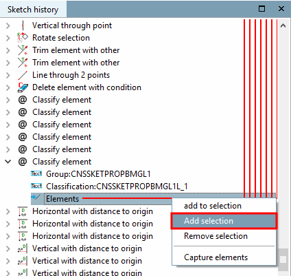
Now classify desired elements.
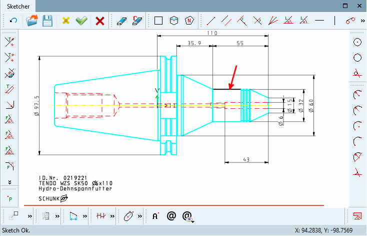
Initial situation: A line not yet classified shall be classified.
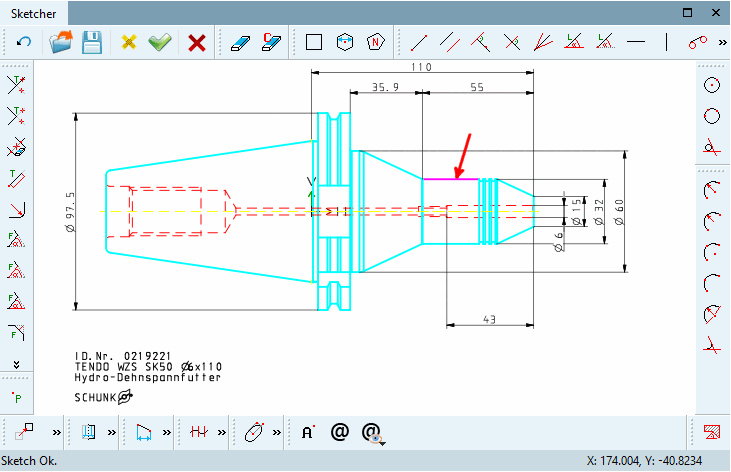
-> Now the line is displayed showing the default highlighting color (purple).
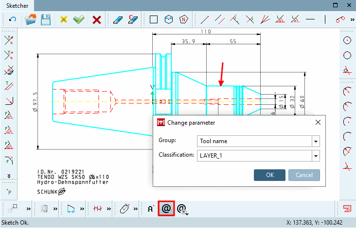
Click on the Classify element icon
 .
.
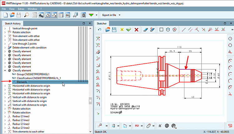
-> The corresponding dialog box for determining the group [Group] and classification [Classification] is opened. Make the desired selections (here tool designation and LAYER_1.
Once selecting a layer, the result to be expected is immediately displayed (line color, type, width).
Finally, confirm your selection by clicking on .
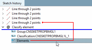
-> In the sketch history [Sketch history], the relationship between shape element and classification is represented by a red arrow.
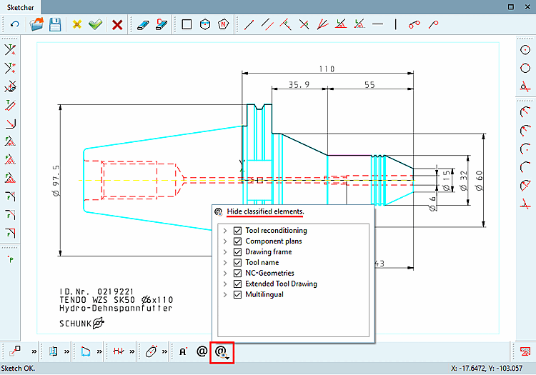
Using Hide classified elements
 you can show and hide all layers of a group or individual layers to check whether everything is set correctly.
-> The respective dialog area is opened.
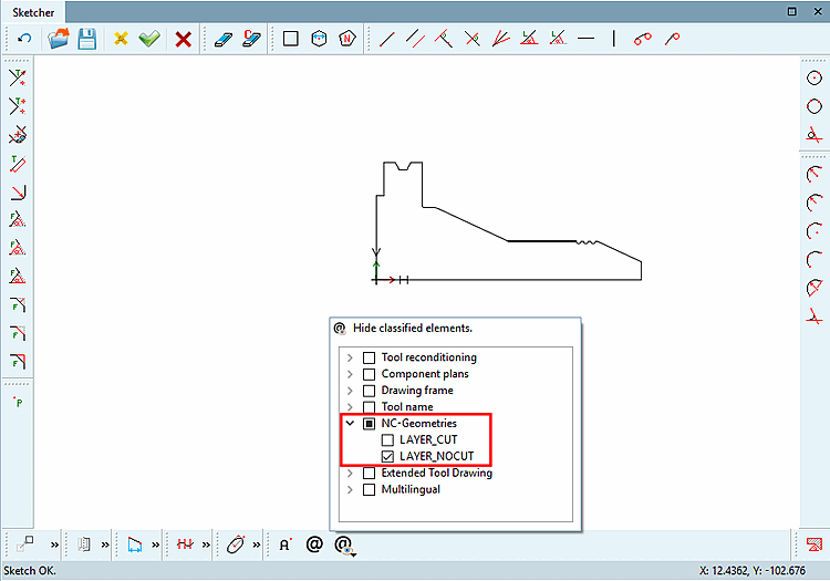
Activate/deactivate the checkbox at desired groups or layers.
Finally, click Apply changes [Accept changes] in the Sketcher.
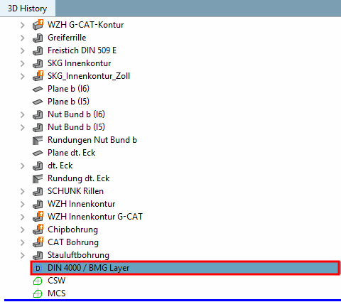
-> The additional 2D drawing with the layer information is displayed in the 3D history [3D History].
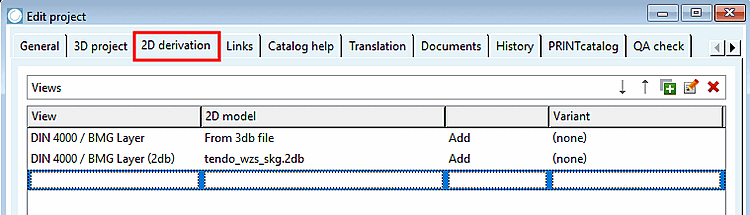
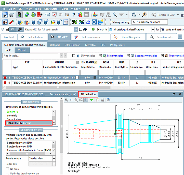
Define in PARTproject -> Edit project -> 2D derivation tab page to display or output the 2D drawing.
-> The additional drawing is displayed under 2D derivation.
![[Note]](https://webapi.partcommunity.com/service/help/latest/pages/jp/ecatalogsolutions/doc/images/note.png)