7.9.3.4.1. Connection points
for assembly construction
7.9.3.4.1.4.
Connection points on miters
|  |
| Prev | Next |
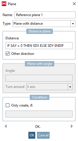
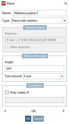
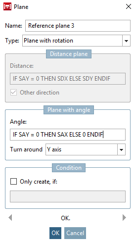
In the variable manager [Variable Manager], add the variables SAX, SAY (start side) and EAX, EAY (end side) for entering the mitre angle ; also SDX, SDY, EDX, EDY with status [Status] feature algorithms [Attribute algorithms] as auxiliary variables for calculating the distance plane [Distance plane] (see figure below).
![Variable manager [Variable Manager]](https://webapi.partcommunity.com/service/help/latest/pages/jp/ecatalogsolutions/doc/resources/img/img_f73ae53cb9f54d54beef81a13ffbf37d.png)
![Feature algorithms [Attribute algorithms] dialog box](https://webapi.partcommunity.com/service/help/latest/pages/jp/ecatalogsolutions/doc/resources/img/img_5237aaf1be2d4c9ca0f02541a301195e.png)
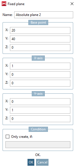
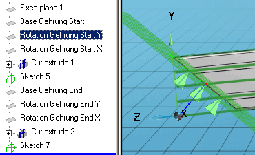
![Fixed plane 1 - Point of impact [Base point]](https://webapi.partcommunity.com/service/help/latest/pages/jp/ecatalogsolutions/doc/resources/img/img_7e7694fbb6074036abad51f1e18bc1b7.png)
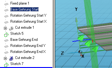
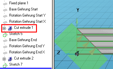
![Extrusion body [Extrusion solid]](https://webapi.partcommunity.com/service/help/latest/pages/jp/ecatalogsolutions/doc/resources/img/img_89c374bad9304b3cae3e3969baca946d.png)
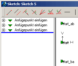
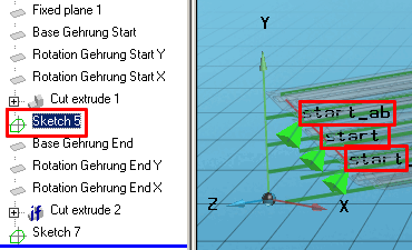
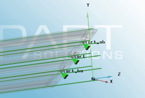
The "End" connection points are created in the same way as described above.