7.9.3.4.1. Connection points
for assembly construction
7.9.3.4.1.3. Alignment of connection points
|  |
| Prev | Next |
The connection points must be created in such a way that the connecting parts have the same orientation. This means that a connecting part must not be rotated by 180°, because the open side of the cable duct must of course always be on the same side.
This is achieved by always having the red axis pointing upwards.
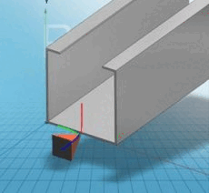
The following illustration shows two parts that are to be connected:
|
|
|
Result: The red axes lie on top of each other, the green and blue axes point in the opposite direction
|
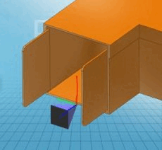
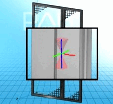
To ensure that fences can be moved around the hinge, the attachment points must be aligned in opposite directions.
Because the red coordinate axes are also superimposed in this example, the corresponding connection point of the right and left fence must be aligned in opposite directions.
One connection point points upwards, the other downwards.
One red axis of the coordinate system points out of the fence, the other points into the fence.
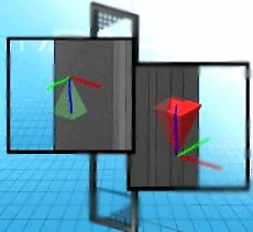
The lever position depends on the orientation of the connection point.
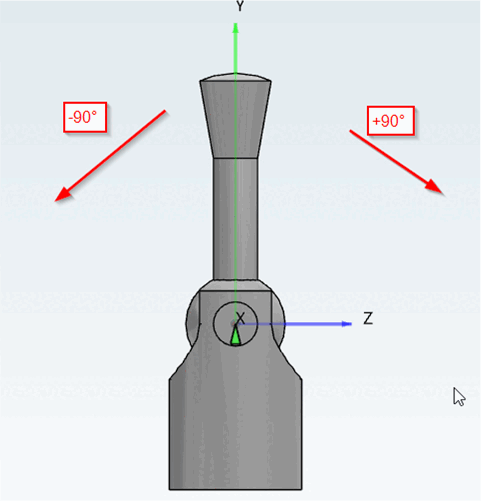
If, for example, the angle of the connection point is left at 0° by default, this can result in an incorrect default position of the element to be moved.
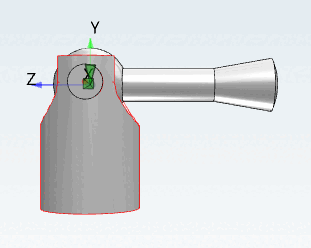
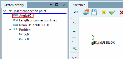
Although the rotation position can be corrected later in the configurator, in the Properties [Rule properties] dialog of the rule [Rule properties], it is much easier (and above all without possible sources of error that can lead to export problems of the component) to set the desired default position using the angle setting in the Sketcher.
Take a look at the example at Section 7.13.5.7.3.1, “Starting Position on Rotation”.