7.13.5.7.3. Context menu
Attachment Point: Examples 7.13.5.7.3.1. Starting Position on Rotation |  |
| Prev | Next |
The Orientation of attachment points in the PARTdesigner and thus the Positioning settings ( rotation [Rotation] / translation with min-max [Min] values) [Max] should be special attention should be paid to the creation of an assembly as simple as possible and to avoid any problems in CAD systems. avoid.
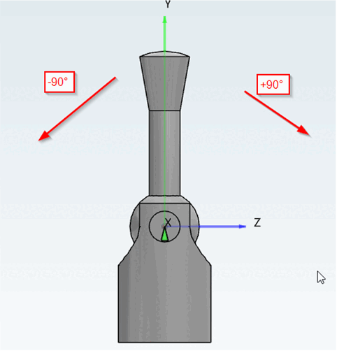
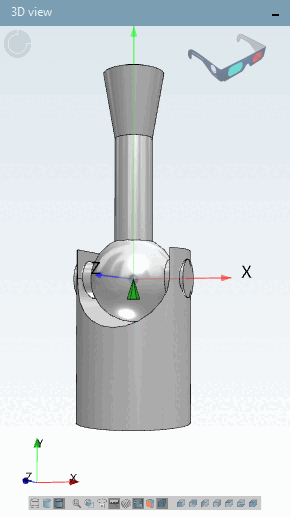
The The following example figure shows a lever with a starting position from 0°. The lever can be rotated from -90° to +90°.
That The following example shows the problem on the basis of the Standard procedure (solution a):
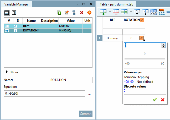
Initial situation in the Variable manager [Variable Manager] with value range dialog in of the table.
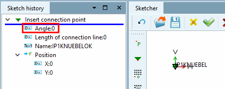
Initial situation in the Sketch: The attachment point to the Component was set with an angle of 0° by default.
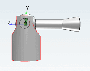
After rotation and min-max values have been set by default, results in an incorrect starting position of the lever (desired is default position to the top).
![[Note]](https://webapi.partcommunity.com/service/help/latest/pages/jp/ecatalogsolutions/doc/images/note.png) | Note |
|---|---|
All settings in the rule's Properties [Rule properties] dialog box are based on the orientation of the attachment point so that default settings are not desired results. | |
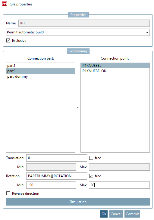
The quick solution would now be a correction of the rotation with "-90".
-90+PARTDUMMY@ROTATION
| Note |
|---|---|
A negative value for manipulation should be should be avoided at all costs so that there are no problems on the part of the CAD system. appear. | |
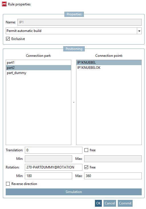
One justifiable, alternative approach looks like this:
270-PARTDUMMY@ROTATION
This
however, it now also requires an adjustment of the min-max values. There PARTDUMMY@ROTATION values from -90 to +90
, the min-max values are 180 and 360.
Min = 270-90 = 180
Max = 270+90 = 360
A lot simpler and without the risk of incorrect settings is the solution b).
Correct the angle of the attachment point (here in the example to the value 90).
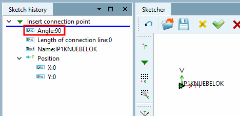
Now , you get the desired one with default settings in the rule's Properties [Rule properties] dialog box Starting position of the lever.