
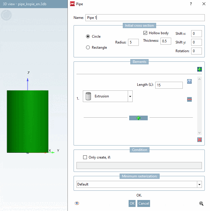
The pipe run can be specified in the Elements section.
Error index
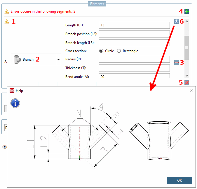
 this icon and its associated label show whether errors are present and, if so, in which element.
Element: Individual element of the pipe run. A pipe run consists of at least one and up to any number of elements. (Theoretically unlimited -> RAM limits the number). Further information on each element type will follow.
Insert new operation below [Add new operation below.]
 (not visible in the figure above)/ Delete this operation [Delete this operation.]

Remove all operations [Remove all operations.]
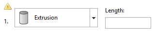
 as a pipe run must consist of at least one pipe, an empty element remains.
Help
 technical drawings help you to fill in the individual fields correctly.

Each input field in this group (exceptions are noted) allows table and/or local variables and expressions (only common PARTdesigner expressions, see Section 10.1, “PARTdesigner-Expressions ”
![Help to "Extrusion [Extrusion] "](https://webapi.partcommunity.com/service/help/latest/pages/jp/ecatalogsolutions/doc/resources/img/img_8f2173ff9a1f4fe28c1aeee04006478d.png)
![Help to "Extrusion [Extrusion] "](https://webapi.partcommunity.com/service/help/latest/pages/jp/ecatalogsolutions/doc/resources/img/img_87d9ad8c838b4019b67d84ed7595c30a.png)
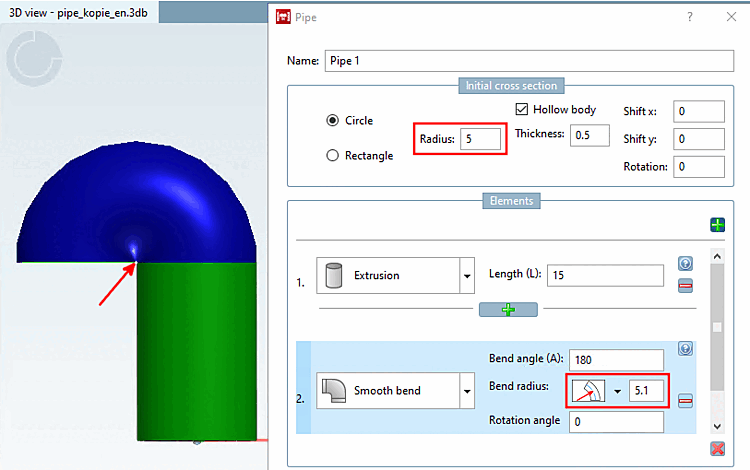
Bending round [Smooth bend] creates a body of rotation.
![Element "Bend round [Smooth bend] "](https://webapi.partcommunity.com/service/help/latest/pages/jp/ecatalogsolutions/doc/resources/img/img_5a9f171fb9a34b2dab4e15e8002c2535.png)
![Help to "Bend round [Smooth bend] "](https://webapi.partcommunity.com/service/help/latest/pages/jp/ecatalogsolutions/doc/resources/img/img_d91b7990116748618f230d83e4fb6050.png)
Bending angle (A) [Bend angle (A)]: Enter an angle that describes how far the pipe should be bent in this element (section of an arc). All values between 0° and 360° are valid.
Bending radius [Bend radius]: Enter the radius of the circle that the pipe follows.
Toggle for radius reference point: With a click on the arrow you can open a list field where you can switch between different modes:
Rotation angle: Specify the angle for the orientation of the pipe run. Any angle between 0° and 360° is valid (360° is then again equivalent to 0°).
![Bending angle [Bend angle] 90°](https://webapi.partcommunity.com/service/help/latest/pages/jp/ecatalogsolutions/doc/resources/img/img_64dde75b134d4f2baca79a2d4de1455a.png)
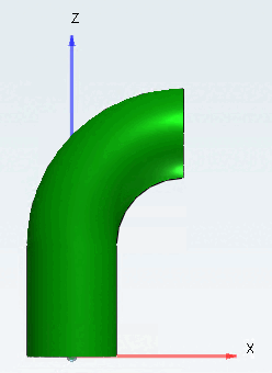
![Bending angle [Bend angle] 180°](https://webapi.partcommunity.com/service/help/latest/pages/jp/ecatalogsolutions/doc/resources/img/img_c271c28d9b8144a99761844c9402e260.png)
![Bending radius [Bend radius] 15 with a bending angle [Bend angle] of 180°](https://webapi.partcommunity.com/service/help/latest/pages/jp/ecatalogsolutions/doc/resources/img/img_bb96a870d56646969783b297b96d726e.png)
![Bending radius [Bend radius] 6 with a bending angle [Bend angle] of 180°](https://webapi.partcommunity.com/service/help/latest/pages/jp/ecatalogsolutions/doc/resources/img/img_ca24d8c27c9145ad981ece6836fb3dce.png)
![[Note]](https://webapi.partcommunity.com/service/help/latest/pages/jp/ecatalogsolutions/doc/images/note.png)


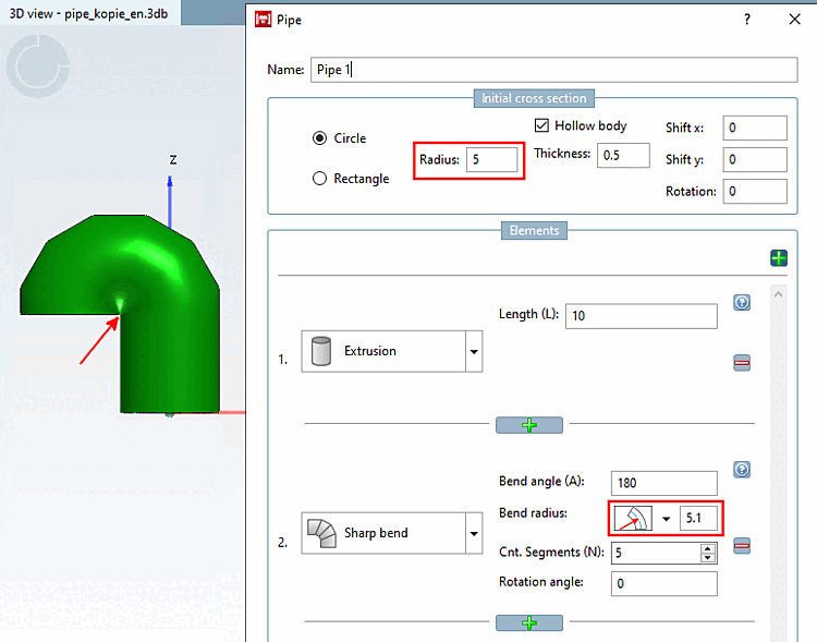
The square bend [Sharp bend] and round bend [Smooth bend] elements are similar, except that the square bend [Sharp bend] is made up of straight tubular elements connected at a certain angle (usually welded in practice).
![Element "Bend angular [Sharp bend] "](https://webapi.partcommunity.com/service/help/latest/pages/jp/ecatalogsolutions/doc/resources/img/img_6e39d1c56e56426abe40e043a6efdbce.png)
![Help to "Bend angular [Sharp bend] "](https://webapi.partcommunity.com/service/help/latest/pages/jp/ecatalogsolutions/doc/resources/img/img_699ccb705f3c4ca4bc131a22f3be31bf.png)
Bending angle [Bend angle]: Enter an angle that describes how far the pipe should be bent in this element (section of an arc). All values between 0° and 360° are valid.
Bending radius [Bend radius]: Enter the radius of the circle that the pipe follows.
Toggle for radius reference point: With a click on the icon, you can switch between different modes:
No. of segments [No. segments]: The number of pipe segments used to approximate a circle. This field does not allow variables or expressions.
Rotation angle: Specify the angle for the orientation of the pipe run.
Valid values depend on the cross-section type. For circular [Circle] type, all values are valid. For the rectangular [Rectangle] type, the values are restricted to 0°, 90°, 180° and 270° due to the need for downward compatibility.
![Bending angle [Bend angle] 90°](https://webapi.partcommunity.com/service/help/latest/pages/jp/ecatalogsolutions/doc/resources/img/img_478b782060fd410ea0d1ce45a2ea1378.png)
![Bending angle [Bend angle] 180°](https://webapi.partcommunity.com/service/help/latest/pages/jp/ecatalogsolutions/doc/resources/img/img_2462258320ab4530b2a286040c33d91f.png)
![No. of segments (N) [Cnt. Segments (N)]: "0"](https://webapi.partcommunity.com/service/help/latest/pages/jp/ecatalogsolutions/doc/resources/img/img_3db8f142f0b141e9a90c93736c70cd14.png)
![No. of segments (N) [Cnt. Segments (N)]: "3"](https://webapi.partcommunity.com/service/help/latest/pages/jp/ecatalogsolutions/doc/resources/img/img_0ea9cc1221674b1cabcb8e383f01bccb.png)
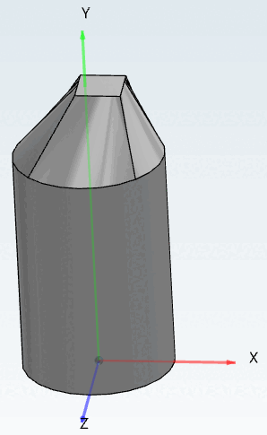
The cross-section change [Cross section change] element allows you to change the shape and/or orientation of the cross-section. The input and output cross-sections will therefore be different. This applies to all of the following elements.
![Element "Change in cross-section [Cross section change] "](https://webapi.partcommunity.com/service/help/latest/pages/jp/ecatalogsolutions/doc/resources/img/img_f53ff579e9af4b4ca9df2be2910a62d1.png)
![Help to "Change in cross-section [Cross section change] "](https://webapi.partcommunity.com/service/help/latest/pages/jp/ecatalogsolutions/doc/resources/img/img_6d2e4e460d474c449ff6cd92c7064e03.png)
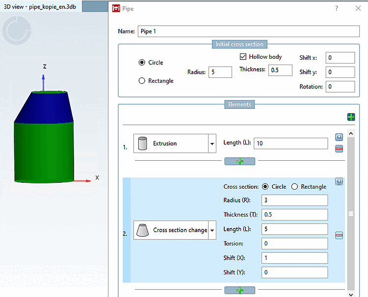
Cross-section [Cross section]: Select the cross-section type (circle [Circle] / rectangle [Rectangle] ).
Radius (R): (cross-section dimension): Define the size of the new cross-section.
Wall thickness (T) [Thickness (T)]: Only active if the entire pipe is hollow (see Fig. „ Initial cross-section [Initial cross section] -> circle [Circle] “). If yes, a value must be entered.
Torsion: Rotation of the cross-sectional plane around its center. The value is limited to a maximum of 180°. However, high values lead to strange solids. Check the result in the preview and, if in doubt, split the element into 2 elements, each with half the length and half the torsion.
The following example shows sweeps with rectangle cross sections.
Displacement: (Displacement X [Translation X] / Displacement Y [Translation Y] ) Enter the corresponding values to determine an off-center cross-section at the end element.
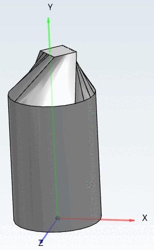
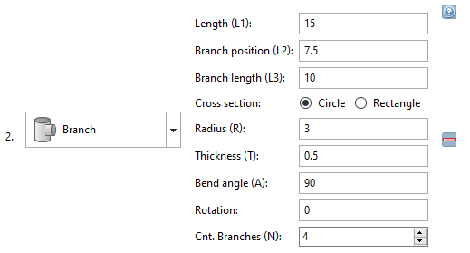
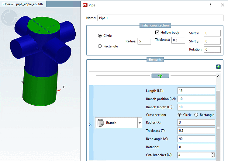
The branching [Branch] element allows you to add separate branches to a pipe. Determine the number and shape of the branching elements. Later, new pipes can be added to each branch.
![Help to "Branching [Branch] "](https://webapi.partcommunity.com/service/help/latest/pages/jp/ecatalogsolutions/doc/resources/img/img_3414319babfb4a71879293e8bb663c30.png)
Length (L1): Length of the main branch.
Branch position (L2): Position of the side branches.
Branch length (L3): Length of the lateral branches.
Cross-section [Cross section] (circle [Circle] / rectangle [Rectangle] ): Select the cross-section type of the side branches.
Determine the radius (R) [Radius (R)] and wall thickness (T) [Thickness (T)] of the side branches. The input field under Wall thickness [Thickness (T)] (T) is only active if the Hollow section [Hollow body] option is activated under Initial cross-section [Initial cross section].
Bending angle (A) [Bend angle (A)]: Represents the angle between the main branch and its side branches. By default, the value is set to "90", which results in a T-shaped branch.
Rotation: Determines the angle for the direction of the first side branch (default 0° corresponds to the direction of the X-axis)
No. of branches (N) [Cnt. Branches (N)]: Determines the number of side branches. The side branches are distributed equally around the main branch. This field does not allow variables or expressions.
Information on how to edit the pipe at branches can be found under Section 7.6.2.11.4, “Context menu commands” -> Branches.