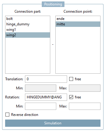
Connection [Connection part] part or connection point [Connection point]:
You can assign connection parts to the currently selected connection point. The selection of part and its connection point is performed via these two fields. For example, in above figure the connection part "part2" with connection point "IP1KNUEBELOK" is assigned.
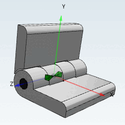
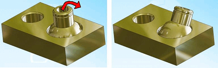
Rotation: Rotation of the component around a connection point (via angular dimension or variables) is possible.
In the Rotation input field, you define the starting position of the moving element in the CAD.
Using the Free [free] option, assembly elements that were transferred from PARTdataManager to a CAD system can be freely rotated around the rotation axis.
If the Free option is activated, a minimum and maximum position can be defined (see next point).
The min [Min] and max specification [Max] is used to specify the restriction in the CAD system. For example, a lever could only move within the set range.
![[Note]](https://webapi.partcommunity.com/service/help/latest/pages/jp/3dfindit/doc/images/note.png)
Note Please also take a look at the example.
The set min and max values for translation and rotation are visualized in the 3D view.
The feature can be configured in the 3D toolbar via Button
 Control Limits
ads [Show rule limits] can be enabled or deactivated. Is it
activated, all control limits for an assembly are
shown.
Control Limits
ads [Show rule limits] can be enabled or deactivated. Is it
activated, all control limits for an assembly are
shown.
Min values are represented by yellowish planes, max values by reddish ones. The respective value is displayed in it or besides.
The current value is represented by an orange dot which is located on an orange line (translation) or arc (rotation).
If there's a formula for one of the variables, the formula's value gets resolved.
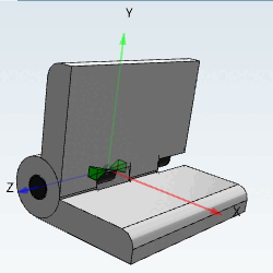
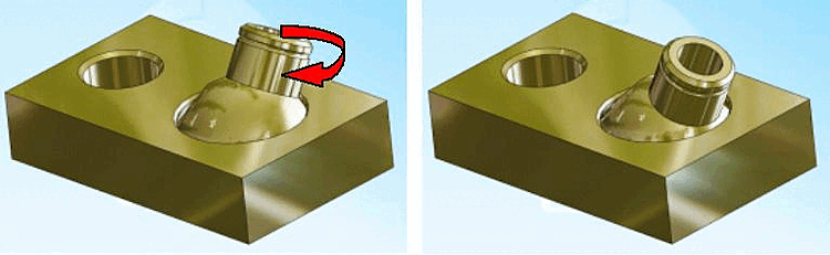
Translation: Distance between two connection points (via value or variable). In the figure below, the profile (later in the CAD system) moves at the distance between connection points 1 and 2.
In the Translation input field, you define the starting position of the moving element in the CAD.
Using the Free [free] option, assembly elements that were transferred from PARTdataManager to a CAD system can be freely rotated around the translation axis.
If the Free option is activated, a minimum and maximum position can be defined (see next point).
The min [Min] and max specification [Max] is used to specify the restriction in the CAD system.
The set min and max values for translation and rotation are visualized in the 3D view. See also above under Rotation.
Reverse direction: The component is rotated by 180 degrees with respect to the Z-axis [Z axis] at the connection point.
Details can be found under Section 3.6, “Simulation”.
Tilt: ... enables tilting at an attachment point.
Pivoting [Swivel] : ...enables swiveling in an inclined position.
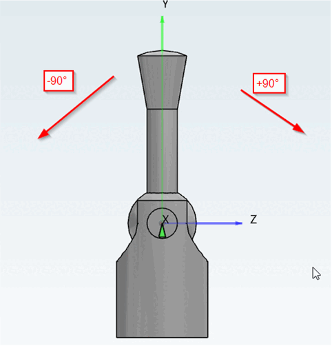
![Example with "Rotation [Rotation] "](https://webapi.partcommunity.com/service/help/latest/pages/jp/3dfindit/doc/resources/img/img_bf319402e3d64274b772576f5b29342d.png)
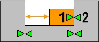
![Example "Translation [Translation] "](https://webapi.partcommunity.com/service/help/latest/pages/jp/3dfindit/doc/resources/img/img_0aa24bd1ba2d42b9a5b334c3fc237f53.png)