|
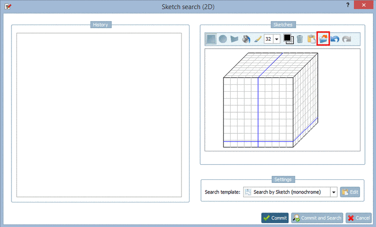
The import of a drawing has been enhanced in the Sketch search (2D).
In the following you can see the procedure:
-> The same-named dialog box opens.
Click on the icon Import drawing and insert the desired image via Explorer. Just as well you can insert the image directly with Ctrl+V.
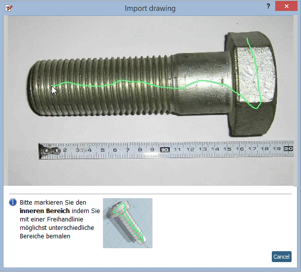
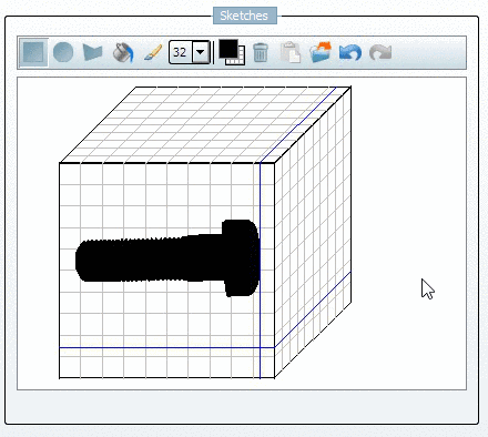
Mark the inner area with a first freehand line:
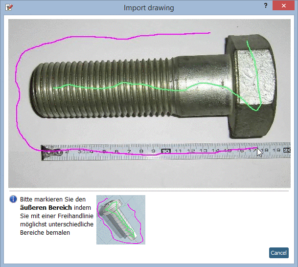
Mark the outer area with a second freehand line:
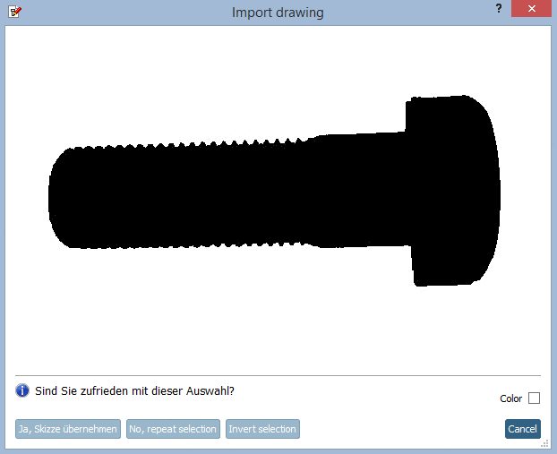
-> As soon as you release the mouse key the result is displayed.
If the result is satisfying click on , otherwise on .
-> The selection is overtaken into the sketcher.