The *.3db object can be dimensioned in the Sketcher using the corresponding tools in the Dimensioning toolbar.
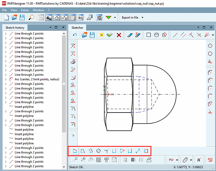
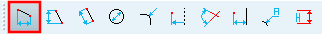
For example, if you want to enter a horizontal dimension (here the total height), click on the Vertical dimension at 2 points [Vertical dimensioning at 2 points] button in the dimensioning toolbar [Dimensioning].
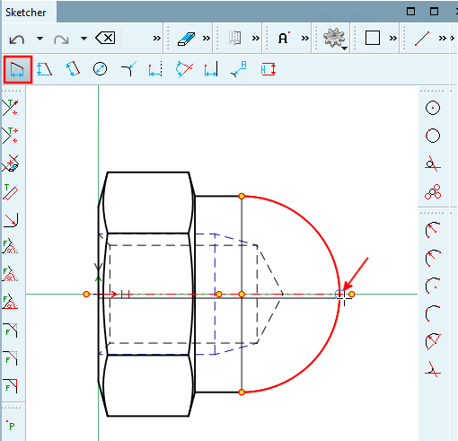
Move the mouse arrow to the first line until the snap appears and fix it by clicking the mouse.
Draw the dimension line at the desired position and fix it by mouse click.
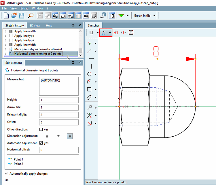
-> The dimensioning becomes visible and the setting parameters for the dimensioning appear in the Edit element docking window.
Determine the single parameters:
By default, "{AUTOMATIC}" is displayed in curly braces.
"AUTOMATIC" takes the current value from the geometry.
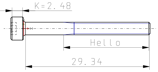
Form the dimension text [Dimension text] statically or dynamically or mixed static-dynamic.
Hello
Dimension text: static-dynamic
K={K}Enter only the desired variable. The respective value is generated dynamically.
{L}Relevant digits: Here you can define the decimal places [Decimal digits] of dimension text [Dimension text].
Other direction: The dimension line is positioned on the other side of the object.
Dimensional alignment [Dimension adjustment]:
Horizontal offset: Determines the horizontal offset of the dimension text from the center point.
![[Note]](https://webapi.partcommunity.com/service/help/latest/pages/jp/partwarehouse/doc/images/note.png)
Note To meet high design requirements, create the dimension drawings externally and make them available as DWG/DXF files, for example. See Section 5.11.2, “ Create and import/convert dimensioning views externally ”.
Dynamic generation of the variable contents in the dimension text is only possible in the manner described above!
Click on the Accept changes
 button.
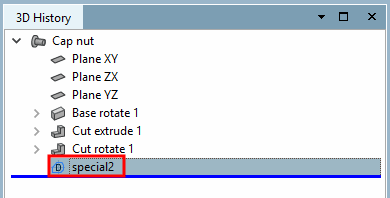
-> The newly created view is displayed in the 3D history [3D History] menu area.
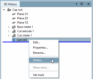
With the context menu command Delete [Delete...]... you can delete the additionally created dimensioning view if necessary.
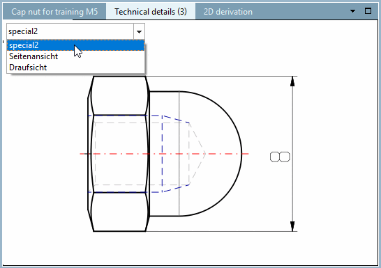
Open the component in the PARTdataManager.
-> The customized dimensioning view is now also available under Technical data [Technical details].
![Dimension orientation [Dimension adjustment]: left](https://webapi.partcommunity.com/service/help/latest/pages/jp/partwarehouse/doc/resources/img/img_b4892e37b97d40f59cf337ebd8580e86.png)
![Dimension alignment [Dimension adjustment]: centered](https://webapi.partcommunity.com/service/help/latest/pages/jp/partwarehouse/doc/resources/img/img_e0dba78551b9493b891a13a98a9c1af1.png)
![Dimension orientation [Dimension adjustment]: right](https://webapi.partcommunity.com/service/help/latest/pages/jp/partwarehouse/doc/resources/img/img_896dd48f55be4124808a1376e140821b.png)