5.12.11.15. Symbol
representations (Circuit symbols) "Advanced"
5.12.11.15.2. Data model
generalized symbol representation / layout |  |
| Prev | Next |
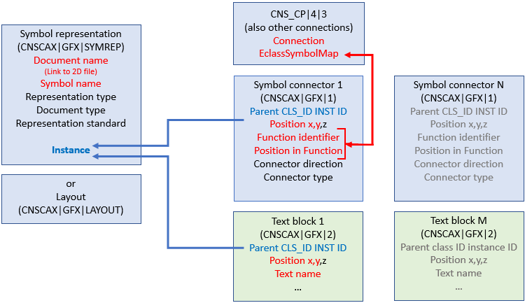
Above diagram shows a fully differentiated symbol representation where especially 2D symbol connectors are connected with 3D connectors. This situation is not specific for electrical components and could also be modified for other types of connections.)
When creating the symbol representation the task now is to achieve different links.
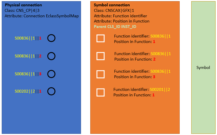
This means that we must link the 2D symbol connection in particular with the associated function and the position in the function. In other words, the task can be expressed by the following sentence: "This 2D connection with the following X/Y coordinates belongs to the Nth function and is the Xth device connection in it." A symbol connection therefore needs 2 indices (function [Function identifier ] and position within the function [Position in Function ]). This is completely analogous to the construction of the Connection EclassSymbolMap attribute in CNS_CP|4|3.
The central pivotal point is the CNSCAX|GFX|1 class (symbol connection ).
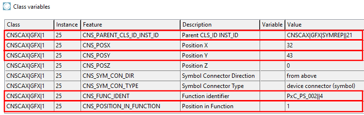
The symbol connection, class CNSCAX|GFX|1 contains ...
... the X/Y coordinates for placing the pin on the 2D symbol graphic in the CNS_POSX and CNS_POSY characteristics,
... in the characteristic Parent CLS_ID INST_ID the reference to the class CNSCAX|GFX|SYMREP, which in turn provides the link to the associated 2D symbol graphic,
... the information for assigning the correct function in the Function identifier feature,
... in the Position in Function feature, the information for assigning the correct position ("pin number") within the corresponding function.