
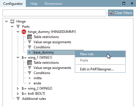
Now rules will be defined which result in the correct creation of an assembly.
At the connection point (  ) of the dummy part
(base_dummy ), the attachment part [Connection part]
"fluegel1 " with its connection point [Connection point]
"middle " is appended using a rule [Rule].
) of the dummy part
(base_dummy ), the attachment part [Connection part]
"fluegel1 " with its connection point [Connection point]
"middle " is appended using a rule [Rule].
Call up the New rule command on "base_dummy".
Select "wing1" under Attachment part [Connection part] and "center" under Attachment point [Connection point].
→ The connection between the connection point "base_dummy" and "fluegel1" is represented by a red arrow line.
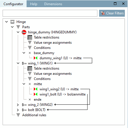
Now use further rules to connect wing1 with wing2 and bolt or alternatively wing2 with bolt.
After all connections are established, the following picture results.
Now set up the configuration in the docking window Structure [Assembly] using the selection list and table row selection alternately.
In order to be able to variably control the angularity, do the following:
For fluegel1, use the context menu of the connection point (
) to open the Rule properties dialog box.
Make the following entry in the Rotation field in the Positioning area:
SCHARNIERDUMMY@ANG
The variable "ANG" takes place in the dummy part which will not be exported but the table of the dummy part will be used by the assembly table project. The control of the angularity occurs this way in the assembly.
Now you can control the opening angle of the hinge with the value range variable "ANG".
If you open the assembly configuration in the PARTdataManager you will see, after selecting the Show assembly structure button
 button, you can see in a graphic how the individual parts are linked to each other via the rules.
![Properties of the rule [Rule properties] " dialog box](https://webapi.partcommunity.com/service/help/latest/pages/jp/installation_ecatalogsolutions/doc/resources/img/img_ce80e91a24fe4462a6ddc6ca9992b048.png)


![[Note]](https://webapi.partcommunity.com/service/help/latest/pages/jp/installation_ecatalogsolutions/doc/images/note.png)
