
The following explains, over which tables the geometric data are connected to the ERP data.
The two most important tables in the LINKDB/PLDBDEMO database model are the LINKTABLE and the ERPTABLE.
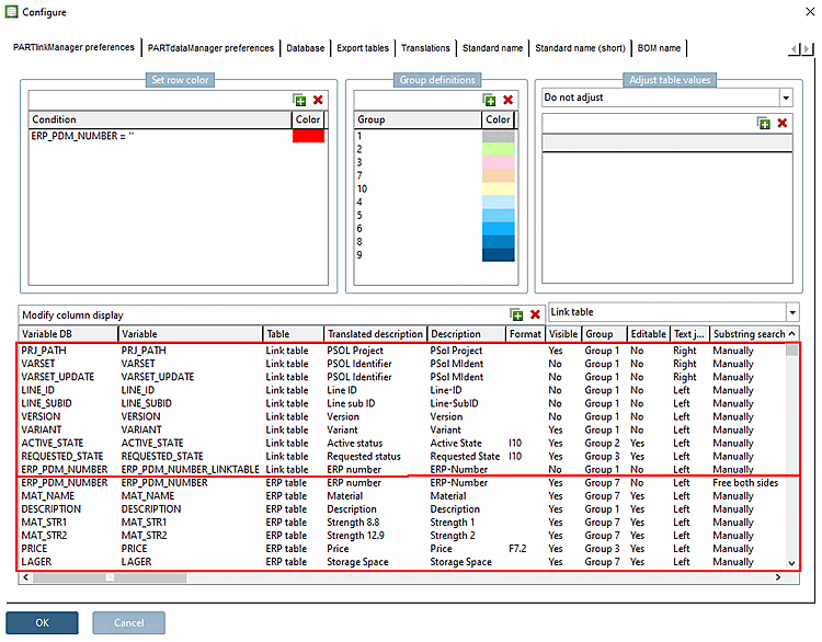
Under PARTlinkManager -> Extras -> Configure ERP environment -> Tab page PARTlinkManager settings [PARTlinkManager preferences] -> Configure column display [Modify column display], the columns of the link table [Link table] and the ERP table are listed. The Table column shows the corresponding assignment.
The ERP table is used to store data from third-party systems.
The table consists of three columns in its basic form. You can apply as many more columns as desired (potential maximum depends on license). These are then inserted in the ERP table.
The columns of the link table [Link table] contain information on which project and which row the characteristic or variation of the component relates to.
The most important columns are:
Consecutive number for user-specific variations of a characteristic within a line ID [Line ID]
For example, a user can define different materials or special measurements outside of the standard, or vary value range fields.
Saves the version of the project.
(The current version is always shown in the PARTdataManager.)
Value range 0/1: If a geometry value of a NON-value range field is changed, the value is set from '0' to '1'. For more information, see:Section 6.1.3.2, “Internal treatment of variants”.
Saves all geometric information of a part; contains all geometric variables with values
The primary key of this table is composed of PSOL project [PSOL Project], line ID [Line ID], line subID [Line sub ID] and version [Version]. This information uniquely identifies a component.