7.13.3. Create Assembly Table Project from A to Z
7.13.3.3. Testing the
Assembly Configuration
|  |
| Prev | Next |
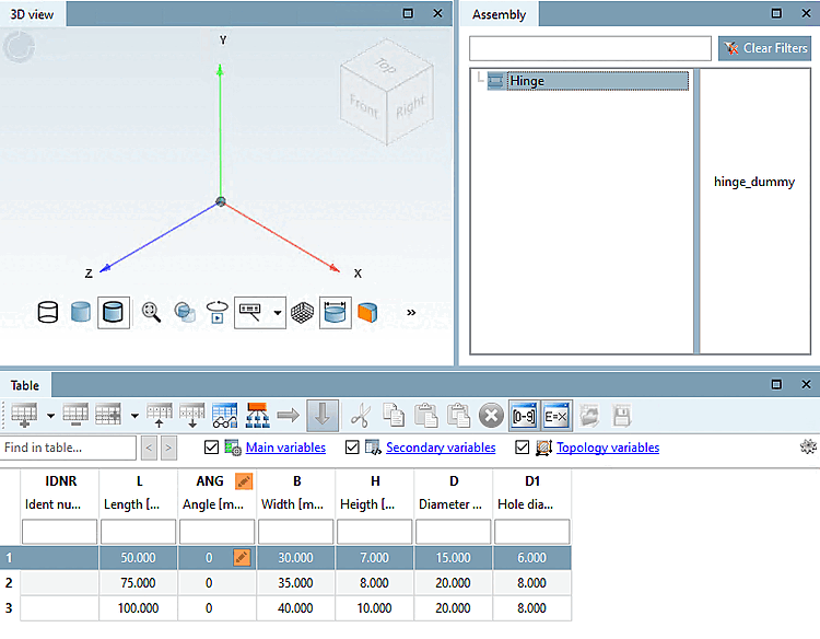
Click on the assembly designation in the docking window Structure [Assembly] (here in the example "Hinge").
→ The start element is displayed (without an image, as it has no geometry).
-> The start element is displayed in red, as it is not yet clearly defined. There are several values in the table, from which you must select one.
Select a table row (a characteristic). This step is mandatory, only then the build up process continues!
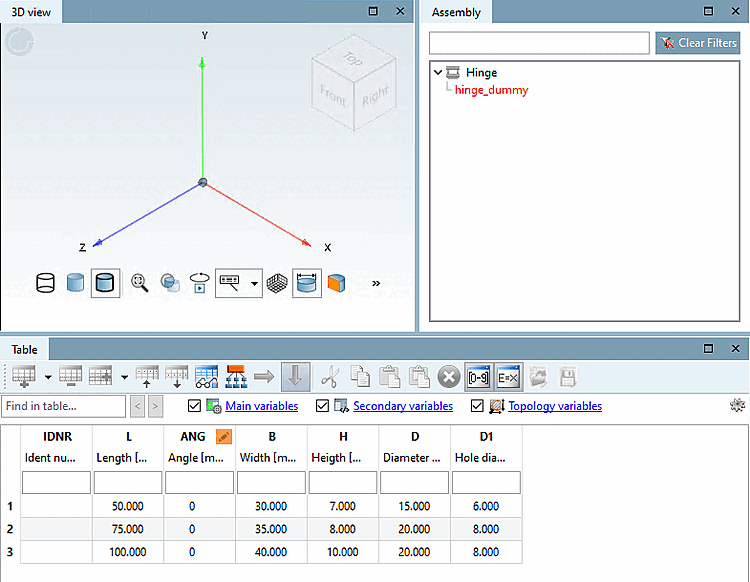
-> The connection point is displayed (here in this example "base_dummy"; it is only one, it could be more as well).
-> At the same time, you will see the connection point in the 3D view.
Green means that there is at least one connection part, but none is yet selected.
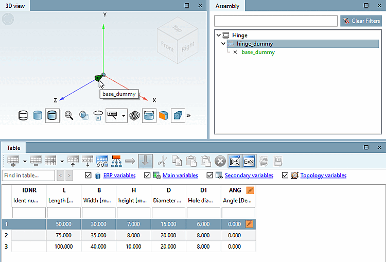
-> Possible parts are shown on the right. In this case only one is possible.
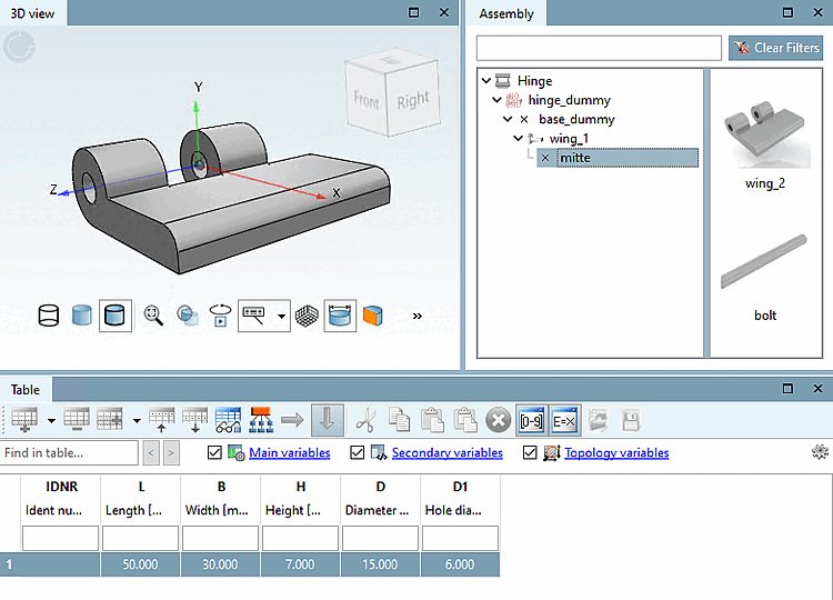
-> The connection point "mitte" and parts available for the assembly are now displayed.
-> The component is displayed in the 3D view.
-> The connection point is shown in yellow. I.e. there are more parts available for this connection point.
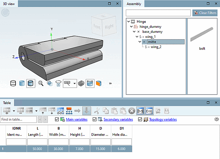
Once again click on the connection point.
-> Other parts still available are shown.
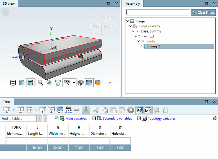
In the described way, insert all listed parts in the assembly.
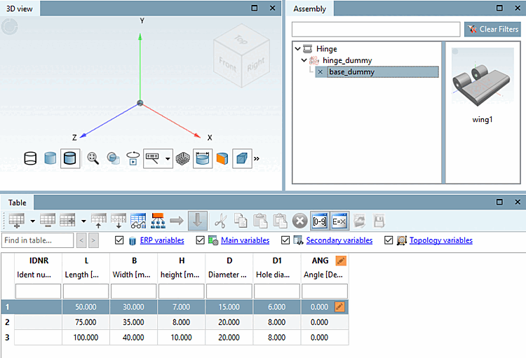
As soon as the structure is complete, i.e. there are no more parts to insert, everything is displayed in black.
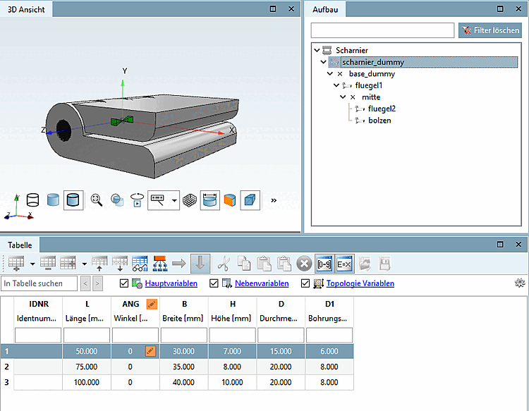
Select "hinge_dummy" in [Assembly] the docking window.
-> The configuration is displayed with table. (Dummy table will be used as assembly table later.)
![[Note]](https://webapi.partcommunity.com/service/help/latest/pages/jp/ecatalogsolutions/doc/images/note.png)
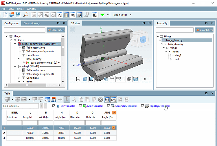
When selecting a table row the assembly is built up accordingly.
(If there is only one row available, the row selection can be left out and the part is immediately inserted.)
The angular position can be controlled via the ANG variable, 90° in the figure above.
In the next step a template is created from the assembly configuration.