The following example shows how to classify a sensor and check the classification in the Mechatronics Concept Designer.
![[Note]](https://webapi.partcommunity.com/service/help/latest/pages/jp/ecatalogsolutions/doc/images/note.png) | Note |
|---|---|
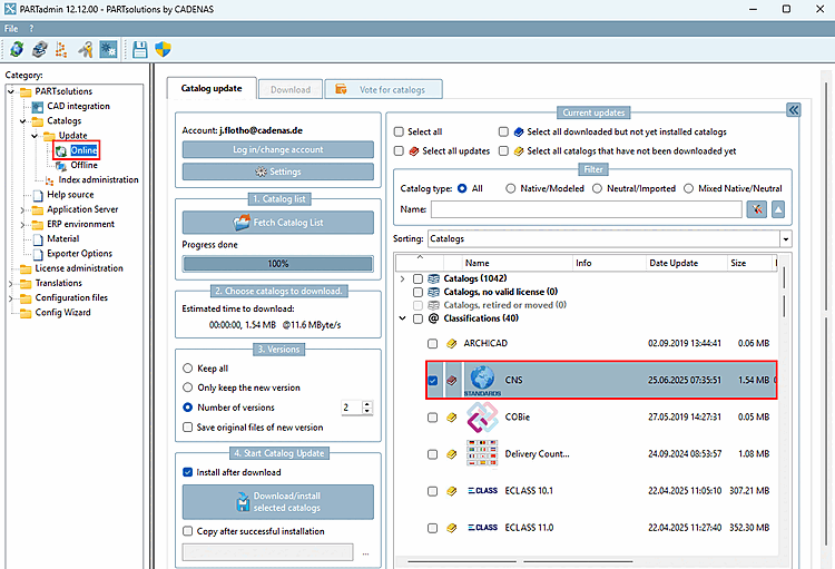
A current CNS classification is required. Install this in PARTadmin under Catalog update -> Online -> Select classifications.
| |
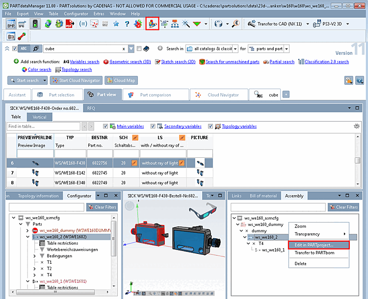
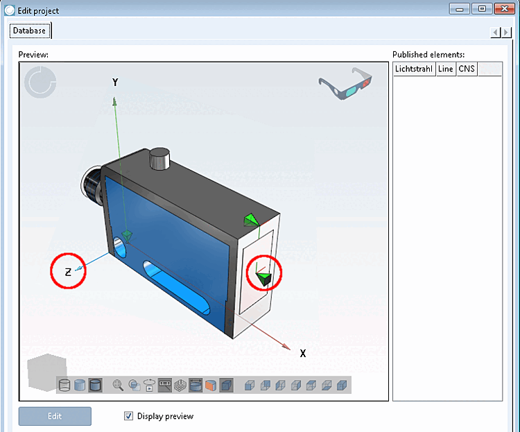
In the configurator [Configurator], select the individual part to be classified in the assembly and open it using the context menu command in PARTproject.
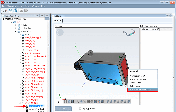
Select the 3db file on the left under Project selection.
-> The preview [Preview] appears on the right under Edit project.
Call up the context menu command Select connection point [Choose connection point] on the feature to be classified (here a connection point).
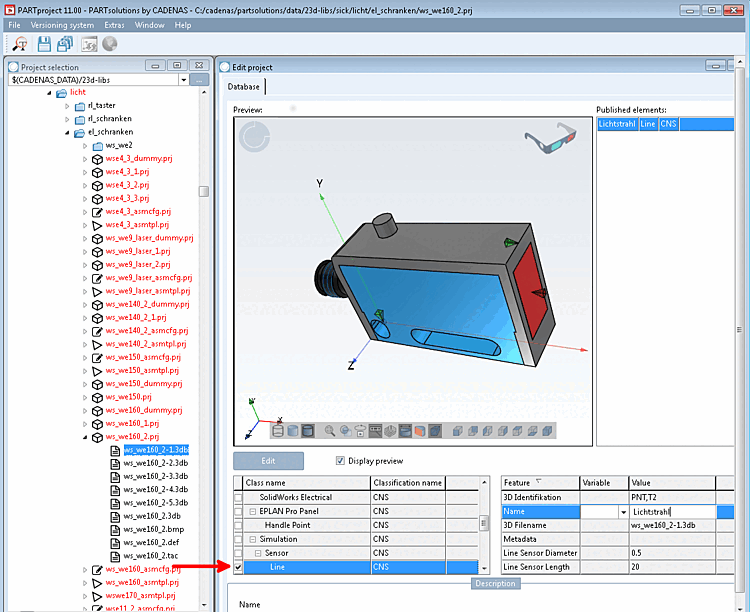
In the case of a sensor, select the class under Simulation -> Sensor -> Line.
-> Beside the selected class the single attributes are displayed.
In the case of a sensor, please set the following values:
Line Sensor Length: Length of the light beam
Scroll down in order to see this attribute.
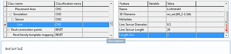
Value range: 0,1,2 (0 for X, 1 for Y and 2 for Z)
For the classification of the light ray a connection point is used. The light ray has to be co-directional to the model's coordinate system. However, connection points have their own orientation (their own coordinate system).
In order to detect the correct attribute value, proceed as follows:
The values for 3D identification and 3D filename are set automatically. Metadata can remain empty.
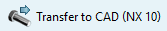
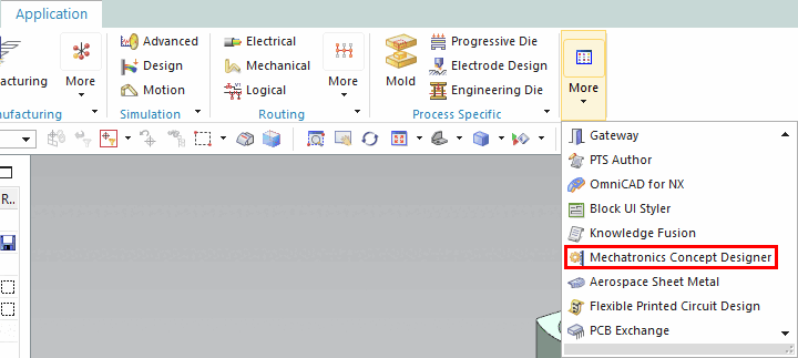
Open the Mechatronics Concept Designer in NX under Application -> More.
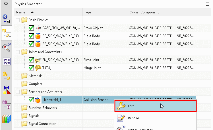
-> Under Sensors and Actuators you can see the classified connection point.
Click Edit in the context menu.
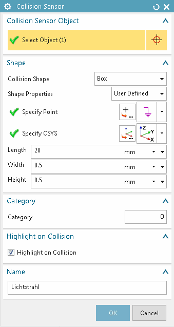
-> The Collision Sensor dialog box opens.
As you can see, Length, Width, Height and Name have been taken from the classification.