
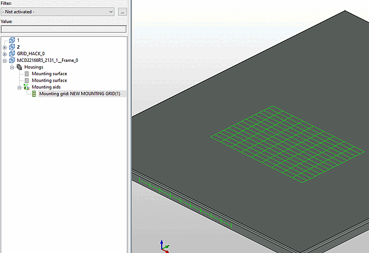
In the enclosure sector, it is often desirable to define certain mounting positions using a periodic 1D, 2D grid. This keeps the classification system lean and in many cases saves hundreds of instances of mounting points. In systems (Zuken, E3) that do not support such grids, a separate slot is created for each grid point during export.
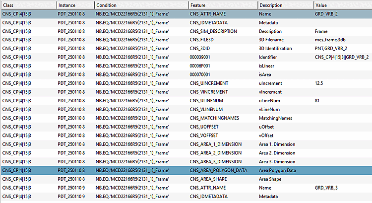
The CNS_CP|4|15|3 class has an analogous structure to the mounting surfaces. The following attributes are specifically important here:
1- or 2-dimensional mounting grid in EPLAN. Placement is only possible at the intersections between the lines.
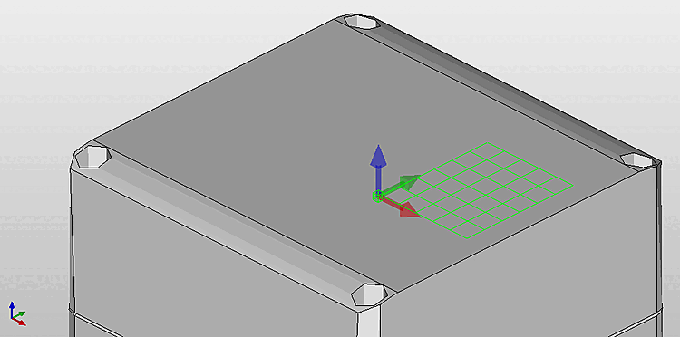
The local (2-dimensional coordinate system) is defined by the connection point, as shown in the image below. The Z axis of the AP (blue) is perpendicular to the mounting plane, the X/Y axes (red/green) define the U and V coordinates. Any offset indicates the distance in the U-V plane between the AP and the first grid point.
Under certain circumstances, even more extensive definitions of mounting grids are required, i.e. in particular a grid of holes or recesses instead of simple points as described above. This is currently only supported by a few target systems. If this feature is really required, it can be defined with the following attributes analogous to "Drilling Contour".