5.12.12. Classify BIM
Parts
5.12.12.2. Classify symbols (DXF/DWG) as "Additional export formats " (manual) |  |
| Prev | Next |
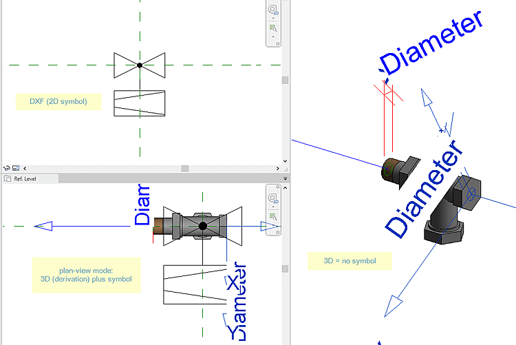
In the following example, the CNSCAX|GFX|LAYOUT class is used.
The following describes the manual process, which can be automated just as well:
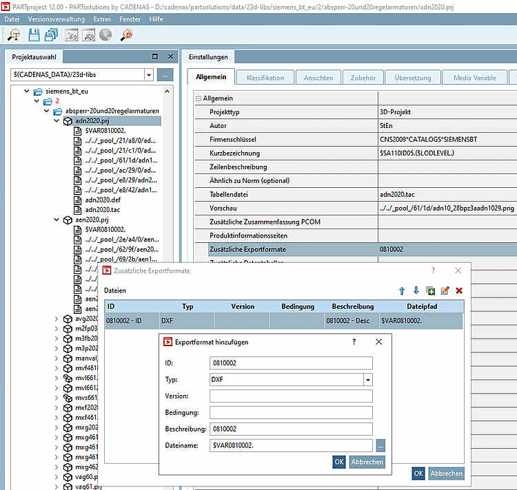
Select the project to which you want to assign a certain symbol as additional export format. (In this example "c2fvvi412020.prj")
Click in PARTproject -> Settings -> General tab -> General menu item -> Additional export formats click on the Browse button
Enter the path to the desired DXF file under Directory path [File path]. (Here $VAR0810002.)
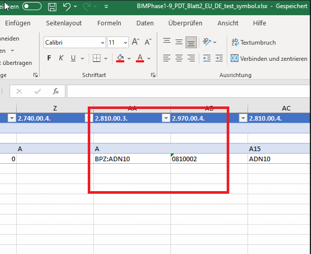
Under ID, enter the unique identifier as it can be found in the source file (e.g. PDT). (Here "0810002".)
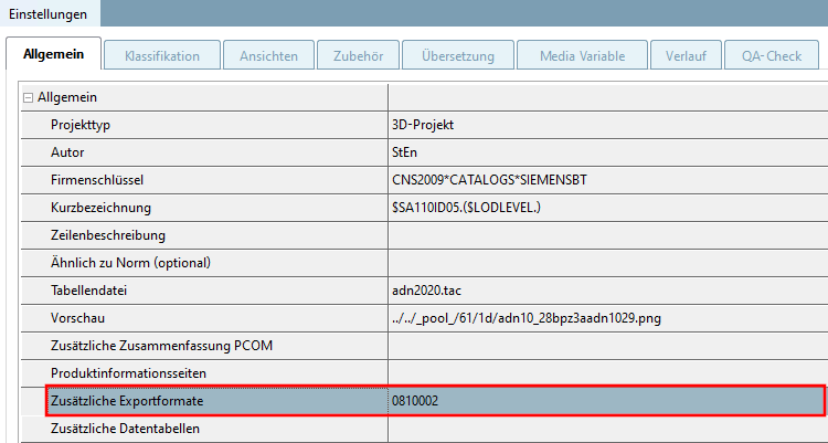
-> The DXF/DWG file is now entered under Additional export formats.
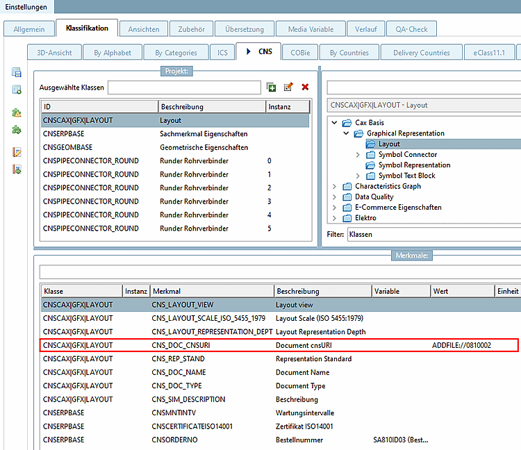
Set the class CNSCAX|GFX|LAYOUT (layout)
Enter the ID of the additional file in feature CNS_DOC_CNSURI using the following syntax.
ADDFILE://ID
If all entries are made, the part can be exported to the CAD.