In assemblies, the selection of certain characteristics does not happen via tables of single parts, but via a superordinated table, which is in the so-called dummy starter part.
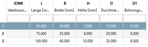
As a basis for this superordinated table (the later assembly table) use the table of a significant single part. Here in this example it is the table of a wing. The variables of the bolt will be brought into dependency to the variables of the wing, so that they don't have to be part of the assembly table explicitly.
Purely module-specific variables are also added to this table, which take over the control of functional features such as angular position or stroke position. In this example, this is the angular position of the hinge. This table is the actual assembly table.
The dummy start part is a 3D project (single part) WITHOUT GEOMETRY (without features), serves as a "start part", contains ONE! active! connection point [Connection point] for the actual assembly and is not exported itself.
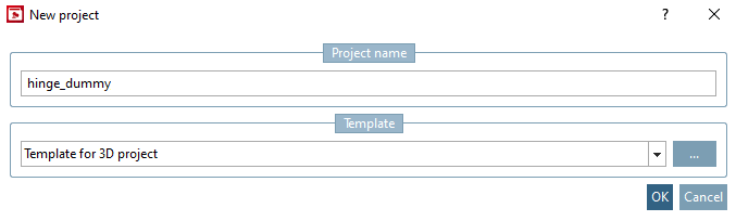
Create a dummy start part as a new project "scharnier_dummy " with template for 3D project [Template for 3D project].
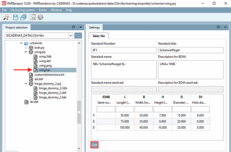
Select the file "fluegel.tac" in "fluegel.prj" and click on in the Settings docking window.
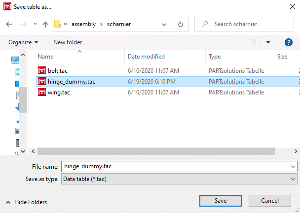
→ PARTdesigner opens. Save the file as "scharnier_dummy.tab or .tac". (Confirm - if the prompt appears - "Replace?" with "Yes").
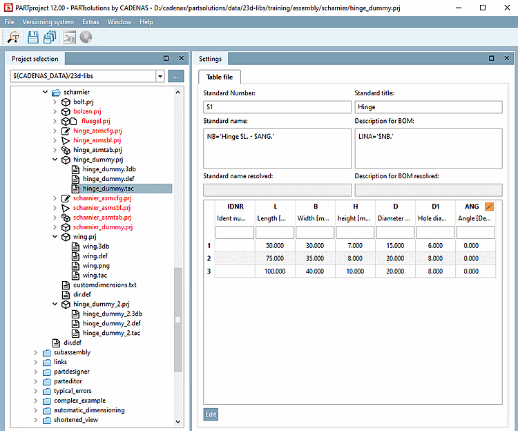
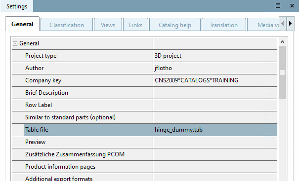
In PARTproject, make sure that the file "scharnier_dummy.tab" is selected in your newly created directory under Settings > General > Table file in the list field.
In PARTproject the file "scharnier_dummy.tab" and click in the Settings docking window.
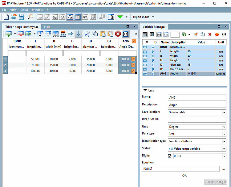
Add a variable ANG to control the angle position of the hinge.
Here in this example following settings are made:
Storage location [Save location]: At the moment, only In table [Only in table] is available. At the latest when you set the connection point, In Geometry and Table [In geometry and table] must be set.
Type identification [Identification type]: Select function characteristic [Function attribute].
Status: Select value range variable [Value range variable]. The opening angle of the hinge can be entered under "ANG".
Formula [Equation]: Select an opening range for the hinge (e.g. 0 to 180 degrees).
[0:180]
NB='Scharnierfluegel $L.$ANG.'
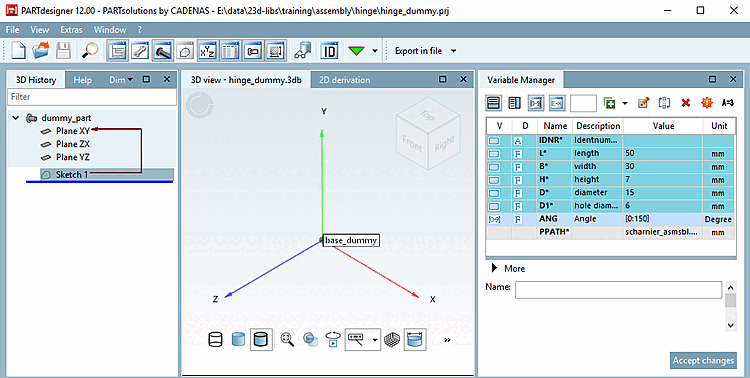
Open "scharnier_dummy.3db" and insert the connection point [Connection point] for the actual assembly.
Apply the change and save the file. Under Storage location, In geometry and table must now be selected.
![Call "New project [New project] "](https://webapi.partcommunity.com/service/help/latest/pages/jp/ecatalogsolutions/doc/resources/img/img_534c3a9c1ec44557a6b8f6fabe68bcec.png)
![[Note]](https://webapi.partcommunity.com/service/help/latest/pages/jp/ecatalogsolutions/doc/images/note.png)