This chapter provides you with an overview of the classification of bolting elements (e.g. own factory standards) according to "CNS classification", including the correct attachment of the connection points.
This prepares the screw connection elements for the desired placement in the assembly.
![[Note]](https://webapi.partcommunity.com/service/help/latest/pages/jp/ecatalogsolutions/doc/images/note.png)
All the important steps are explained below:
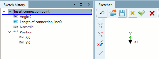
Creation of the connection points in PARTdesigner:
Position, orientation, number and designation (overview)
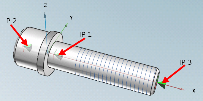
The following illustration uses the example of a cylinder head screw to show which connection points are present, how they must be aligned and where they must be positioned.
Detailed information on all screw fittings can be found at Section 5.12.3.6.1.1, “Attachment points on screw connection elements ”.
Further information on connection points in general can be found under Section 7.9.3.4.1, “Connection points for assembly construction ”.
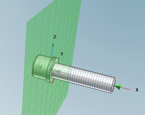
Alignment: The tip of the connection point (green pyramid) points to the support surface. Any other connection points are aligned in the same way. The longitudinal axis of the connection point corresponds to the X-axis.
The sketch lies on a plane perpendicular to the x-axis.
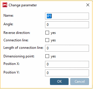
The name is entered in the Change parameters [Change parameter] dialog, otherwise no further changes are made.