
All the steps required to display an alternative abbreviated 2D view will be explained in detail using an example. To illustrate the effect, a greatly simplified block cylinder has been selected. The cylinder length ('HUB') is to be displayed in a shortened alternative. This requires two additional variables as control variables [Control variable] (here in the example 'HUB2D') and as default values for control variables [Default value for control variable] (here in the example 'XHUB'). After activating the Optimize drawing view on sheet [Optimize drawing view on paper size] option, the value of the XHUB variable is used to calculate the cylinder length in the 2D view.
![[Note]](https://webapi.partcommunity.com/service/help/latest/pages/jp/ecatalogsolutions/doc/images/note.png) | Note |
|---|---|
The example can be found in the training catalog under "shortened_view_2". At first a part is designed, then this is used in an assembly. | |
As starter a cylinder with the variables 'HUB' for length and 'D' for diameter is used.
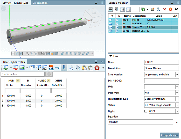
Expand the table in PARTdesigner:
Create the alternative variable for the shortened 2D view, which is entered in PARTproject as a control variable [Control variable] (in the following example 'HUB2D')
Create a variable as the default value for the control variable [Default value for control variable] (in the following example 'XHUB').
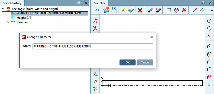
Adjust the length of the cylinder.
For the length 'HUB' had been used by default.
In the Width input field, do not use the entry 'HUB' as usual, but the following entry with a condition:
IF HUB2D = 0 THEN HUB ELSE XHUB ENDIF
If 'HUB2D' equals '0' (this is the default state), then the variable 'HUB' is used.
By activating the option Optimize drawing view on sheet [Optimize drawing view on paper size], HUB2D is set to a value not equal to '0'. This is the reason why the variable must not have a fixed value, but must be declared as a value range variable.
However, if HUB2D is not equal to '0', then 'XHUB' is used to calculate the width [Width].
Set the connection points. These may also be used for automatic dimensioning.
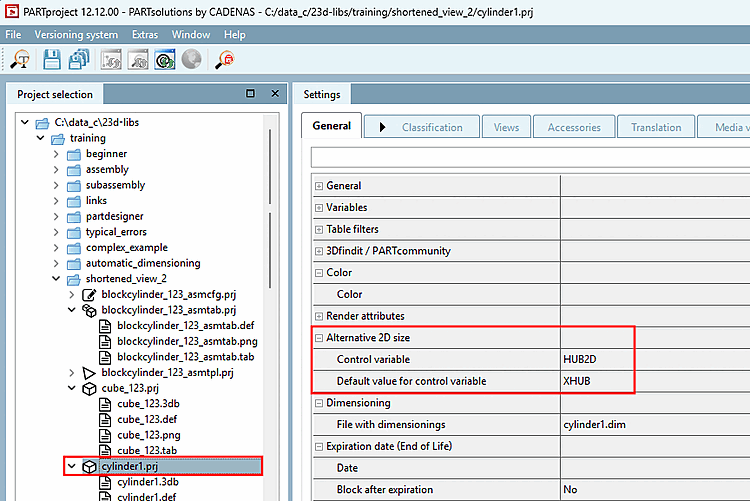
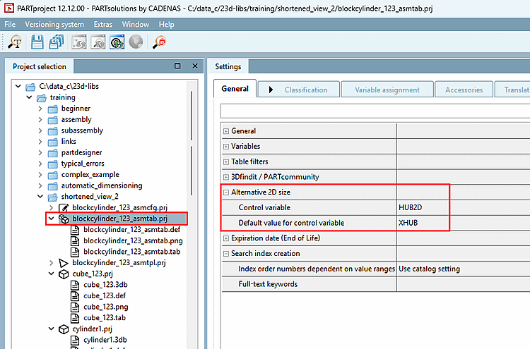
Set the following entries for the cylinder project under PARTproject -> Edit project -> General tab -> Alternative 2D size section:
that in PARTdataManager, in the 2D view, the option field Optimize drawing view on sheet [Optimize drawing view on paper size] (Shortened view [Shortened view] ) is not grayed out but can be activated
Optimize drawing view on sheet [Optimize drawing view on paper size] (shortened view [Shortened view] )
that the alternative variable (control variable [Control variable] ) is calculated internally in the program.
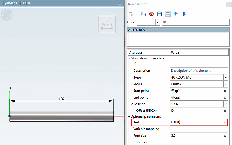
Optionally, you can set automatic dimensioning. The displayed dimension should not change when the shortened view is switched on! For this reason, no IF condition is used for text [Text], not even {AUTOMATIC}, but '{HUB}'.
A detailed description of automatic dimensioning can be found under Section 7.16, “ Docking window "Dimensions " ”.
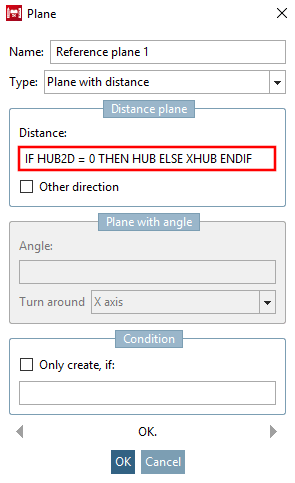
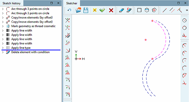
To visualize the abbreviated view [Shortened view], insert a sketch with a "cosmetic drawing" on the same layer as the one used for the main sketch (here in the example Plane XY ).
Use the function Arc over 3 points on perimeter [Arc through 3 points on circle] for an arc line.
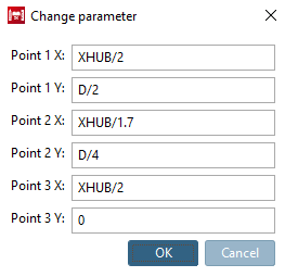
For the positioning of the points, use the variable for the shortened hub ("XHUB").
XHUB/2
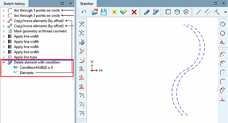
To ensure that the guidelines are only visible when the Optimize drawing view on sheet [Optimize drawing view on paper size] option is activated, use the Conditionally delete element [Delete element with condition] function with the following condition:
HUB2D = 0
'HUB2D=0' is according to the default setting. In this case it shall be deleted. Only if the value of variable 'HUB2D' is unequal to '0', the sketch shall not be deleted, meaning the cosmetic drawing shall be visible.
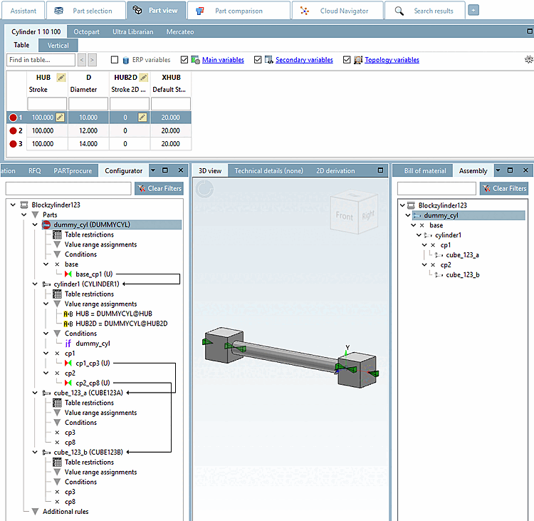
Now the cylinder is used in an assembly. In this example a vastly simplified configuration consisting of one cylinder and two blocks is used.
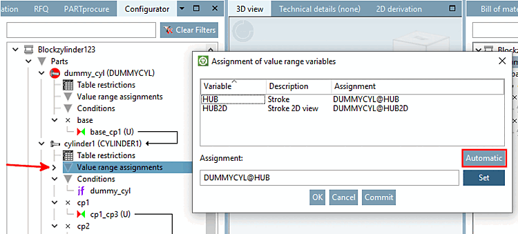
As the cylinder contains value ranges (HUB and HUB2D), please remember to make the value range assignments [Value range assignments].
This time, enter the alternative 2D size [Alternative 2D size] for the assembly.
Test the alternative 2D size for the assembly.
"Optimize drawing view on sheet [Optimize drawing view on paper size] " ( "Shortened view [Shortened view] ") deactivated
"Optimize drawing view on sheet [Optimize drawing view on paper size] " ( "Shortened view [Shortened view] ") activated
![[Important]](https://webapi.partcommunity.com/service/help/latest/pages/jp/ecatalogsolutions/doc/images/important.png)
![Optimize drawing view on sheet [Optimize drawing view on paper size] (shortened view [Shortened view] )](https://webapi.partcommunity.com/service/help/latest/pages/jp/ecatalogsolutions/doc/resources/img/img_10ff36fb96fb43e696cbc2e14477afaa.png)
![Optimize drawing view on sheet [Optimize drawing view on paper size] (shortened view [Shortened view] ) switched off](https://webapi.partcommunity.com/service/help/latest/pages/jp/ecatalogsolutions/doc/resources/img/img_4edf82e5e60444a990eca55701dc69a8.png)
![Optimize drawing view on sheet [Optimize drawing view on paper size] (shortened view [Shortened view] ) switched on](https://webapi.partcommunity.com/service/help/latest/pages/jp/ecatalogsolutions/doc/resources/img/img_094ce8f7d6d84bd493e1717f95ec4976.png)
!["Optimize drawing view on sheet [Optimize drawing view on paper size] " ( "Shortened view [Shortened view] ") deactivated](https://webapi.partcommunity.com/service/help/latest/pages/jp/ecatalogsolutions/doc/resources/img/img_f72bb2b4b8244611a3f767674d24ec52.png)
!["Optimize drawing view on sheet [Optimize drawing view on paper size] " ( "Shortened view [Shortened view] ") activated](https://webapi.partcommunity.com/service/help/latest/pages/jp/ecatalogsolutions/doc/resources/img/img_dadb11055017479ba4c618bc81302375.png)