
For the placing of electrical engineering components in CAD the following shall apply:
The connection point [Connection point] is in the bottom left-hand corner of the bounding box of the component (smallest possible cuboid enclosing the component with alignment along the X,Y,Z axes).
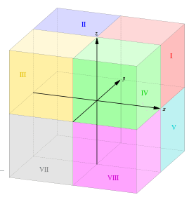
All axes of coordinate system are positive and Z axis point is oriented upwards (as in first octant).
Imagine the 3 dimensional space divided in 8 octants: The 1. octant (I) consists of points where all have three positive coordinates x,y,z.
In most cases, it will be necessary to move the component in the direction of the X, Y and Z axes in order to achieve correct component placement.
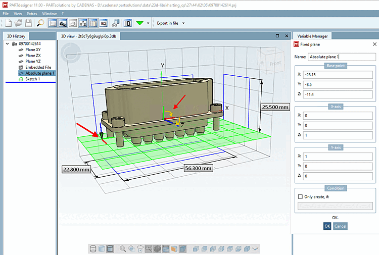
You can implement translation and rotation using the Absolute plane [Fixed plane] dialog.
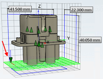
In the following example illustration, you can see a component with the correct alignment (Z pointing upwards), so that only one shift needs to be made (see entries under Point [Base point] ). As the Z-axis is pointing upwards, no axis rotations need to be made. The input fields under X-axis [X axis] retain the default values 1,0,0. The input fields under Y-axis [Y axis] retain the default values 0,1,0.
![The point of origin [Base point] of the absolute plane is in the lower left, rear corner of the bounding box](https://webapi.partcommunity.com/service/help/latest/pages/jp/ecatalogsolutions/doc/resources/img/img_e149ae15e3b045fb96225f28a440e62e.png)
The point of origin [Base point] of the absolute plane is in the lower left, rear corner of the bounding box
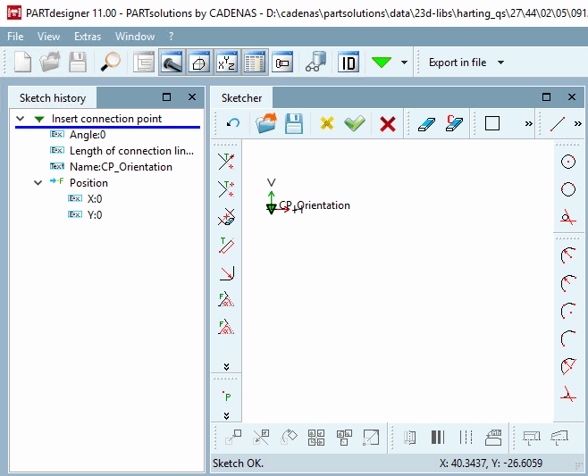
The connection point can be set with angle [Angle] 0, as no rotation is to be carried out, or rotations are realized via the plane.
The coordinates of the connection point under "Position [Position] " can be left at 0.0 so that the connection point is at the point of origin [Base point] of the plane.
![[Note]](https://webapi.partcommunity.com/service/help/latest/pages/jp/ecatalogsolutions/doc/images/note.png) | Note |
|---|---|
Alternatively, a necessary shift can also be made here in the sketch instead of via the Absolute plane [Fixed plane] -> Point [Base point] dialog. | |
For components with incorrect orientation, make appropriate adjustments in the Absolute plane [Fixed plane] dialog under X-axis [X axis] and Y-axis [Y axis].
After the transformation (rotation + displacement) applies:
Example with rotation: The transformation happens with 2 rotations.
The original X-axis [X axis] is placed on the Z-axis (Z=1) and then the original Y-axis [Y axis] is placed on the X-axis (X=1).
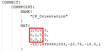
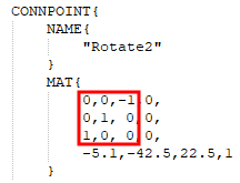
In an exported PS3 file you can check orientation and shift of connection point:
Example 1 (no rotation of axes):
x axis is mapped to x axis, y axis is mapped to y axis, z axis is mapped to z axis.
The lowest line shows the shift in direction of x, y and z axis.
Example 2 (with rotation of axes):
x axis is mapped to the negative z axis, y axis is mapped to the y axis, z axis is mapped to the x axis.
The lowest line shows the shift in direction of x, y and z axis.
The connection point [Connection point] must now be classified.