2.1.9.2. Export 2D
formats
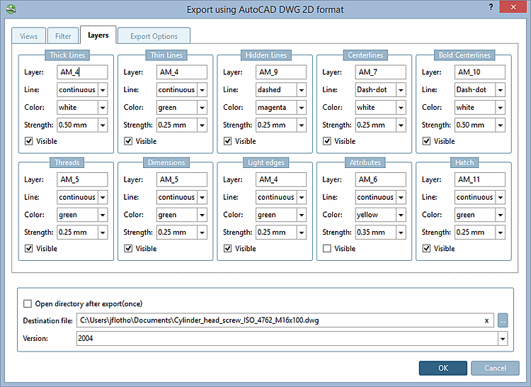
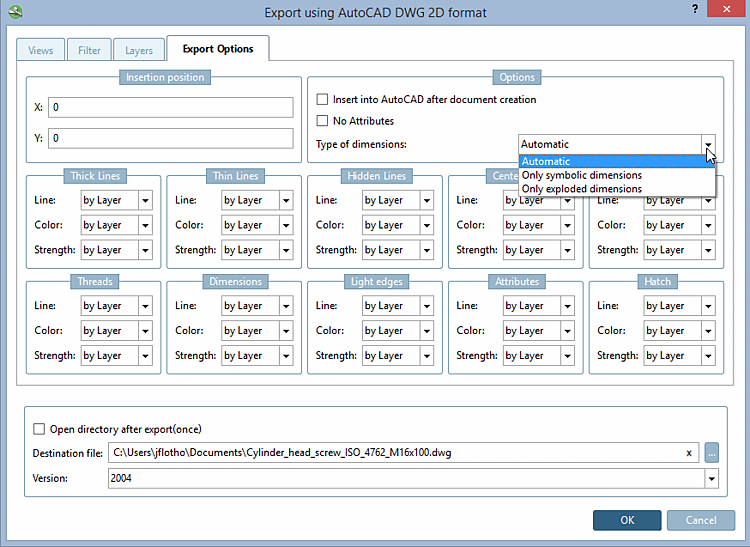
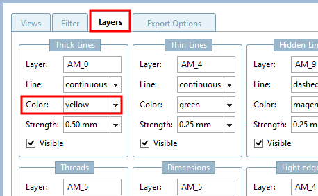
2.1.9.2.3. Tab page "Layers " and "Export options " - AutoCAD DWG 2D |  |
| Prev | Next |
![[Note]](https://webapi.partcommunity.com/service/help/latest/pages/jp/ecatalogsolutions/doc/images/note.png)
Insertion position: The insertion position in the CAD system can already be defined in 3Dfindit - provided your CAD system supports this function. Enter the X and Y coordinates.
Then insert into the active AutoCAD application [Insert into AutoCAD after document creation]:
Do not generate attributes [No Attributes]: ...prevents certain attributes (e.g. texts from PARTproject) from being transferred to the CAD system during export.
Type of dimensions [Type of dimensionings]:
If a symbolic dimensioning can be created then it is used, otherwise the exploded.
Symbolic dimensions [Only symbolic dimensions] only:
A dimensioning created in eCAT for the component or a dimensioning created in the PARTdataManager before the export is recognized as such.
When using this option the dimensioning is created as "real" dimensioning. After selection the respective dialog is displayed.
Resolved dimensions [Only exploded dimensionings] only:
Dimensioning and text are only displayed as exploded elements.
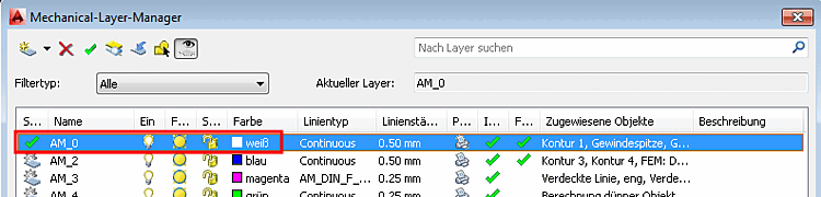
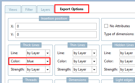
By default, the settings are set to by layer. The color and line settings are thus a) dependent on the layer settings in the CAD system or b) on the settings on the Layers tab page. You can explicitly select other settings for lines and colors in the list boxes, which overwrite the layer settings.