3.1.9.2.8.  Export options " tab page - SVG 2D

[Note]Note
  • When exporting to the svg file, the information on the Layers tab page is stored in the file.

    Example: "Thick lines" are mapped to layer "AM_0" and are stored in the svg file in yellow.

    Example: "Thick lines" are mapped to layer "AM_0" and are stored in the svg file in yellow.

    If the file is imported into an existing drawing, then CAD settings have priority.

    Example: Mechanical-Layer-Manager: AM_0 = white. The inserted part is depicted with white "Thick lines".

    Example: Mechanical-Layer-Manager: AM_0 = white. The inserted part is depicted with white "Thick lines".

    If the file is opened apart, then the depiction will be with the layer color specified in the svg file.

  • Layers not existing in the CAD are created according to the defaults.

  • If you want to overwrite CAD layer information, use the Export options tab page.

    Example: In this case the "Thick lines" are depicted in blue.

    Example: In this case the "Thick lines" are depicted in blue.

  • Levels [Layers] tab page

    Layers " tab page - SVG 2D

    Layers " tab page - SVG 2D

    • Open directory after export(once)

    • Destination file

    • Version

  • Export options tab page

    Export options " tab page - SVG 2D

    Export options " tab page - SVG 2D

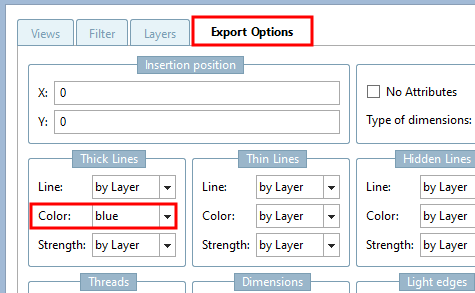
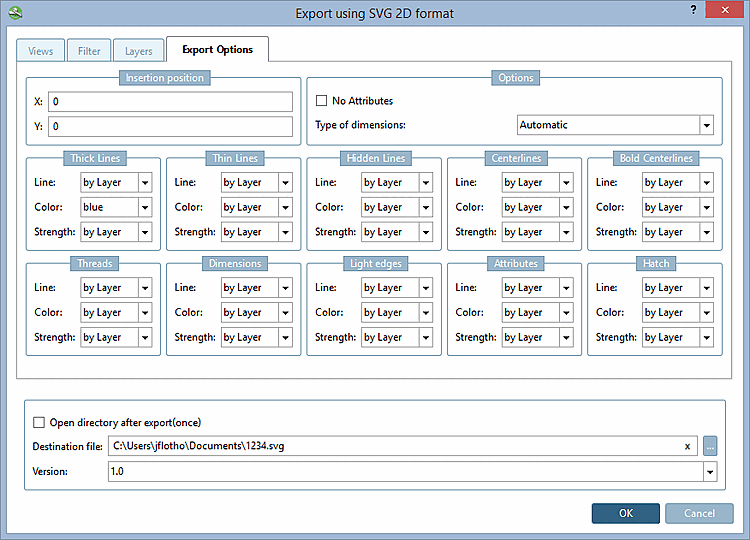
    • Insertion position: The insertion position in the CAD system can already be defined in PARTsolutions - provided your CAD system supports this function. Enter the X and Y coordinates.

    • Do not generate attributes [No Attributes] ...prevents certain attributes (e.g. texts from PARTproject) from being transferred to the CAD system during export.

    • Line and color settings:

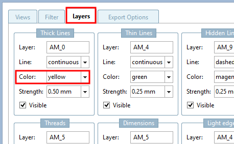
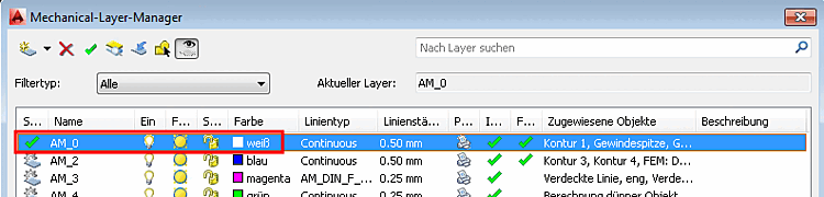
      In addition to the option of specifying certain lines and colors directly, you can also make the color and line setting dependent on the layer setting in the CAD system. To do this, select the "by layer " setting.

    • Open directory after export(once)

    • Destination file

    • Version